
Air inlet lip structure

A technology of air inlet and lower lip, which is applied in the direction of jet propulsion device, gas turbine device, machine/engine, etc., can solve the problem of engine not working normally, and achieve the effect of good propulsion matching performance

Inactive Publication Date: 2018-03-23
SHENYANG AIRCRAFT DESIGN INST AVIATION IND CORP OF CHINA
View PDF4 Cites 3 Cited by
  • Summary
  • Abstract
  • Description
  • Claims
  • Application Information

AI Technical Summary

Problems solved by technology

For fighter jets with high maneuverability, the inlet design needs to avoid lip separation and cause the engine to not work properly

Method used


Image

  • Air inlet lip structure
  • Air inlet lip structure
  • Air inlet lip structure

Examples


Embodiment Construction

[0029] In order to make the objectives, technical solutions and advantages of the present invention clearer, the technical solutions in the embodiments of the present invention will be described in more detail below in conjunction with the drawings in the embodiments of the present invention. In the drawings, the same or similar reference numerals denote the same or similar elements or elements having the same or similar functions throughout. The described embodiments are some, but not all, embodiments of the invention. The embodiments described below by referring to the figures are exemplary and are intended to explain the present invention and should not be construed as limiting the present invention. Based on the embodiments of the present invention, all other embodiments obtained by persons of ordinary skill in the art without creative efforts fall within the protection scope of the present invention. Embodiments of the present invention will be described in detail below ...


PUM


Abstract

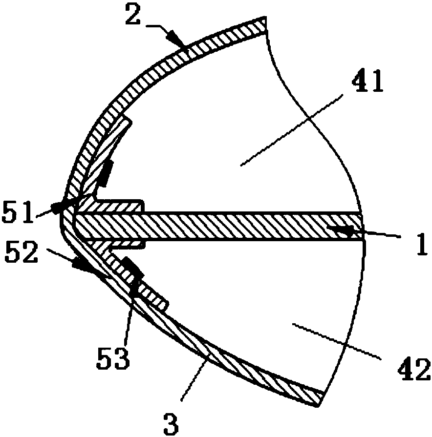
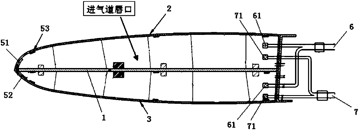
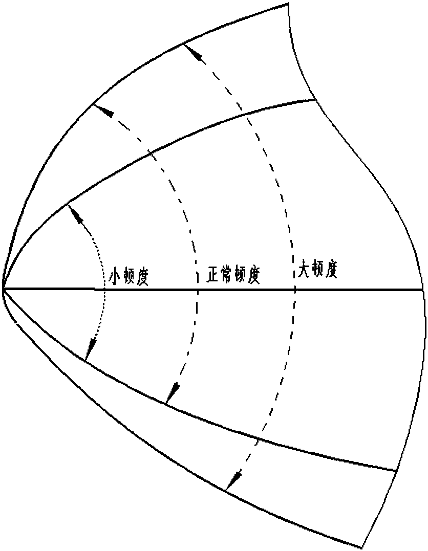
The invention relates to design of a high performance supersonic inlet, and in particular to an air inlet lip structure. The structure comprises an air inlet lip body formed by a support plate, an upper flexible skin and a lower flexible skin, an upper cavity, a lower cavity, an upper lip margin driving part, a lower lip margin driving part and a temperature controlling device, wherein one end, which is close to lip margins, of the support plate is formed by shape memory alloy which has at least two change states to ensure that the air inlet with the air inlet lip structure has a normal state,an opening enlarging state and an opening shrinking state; the upper lip margin driving part and the lower lip margin driving part are both formed by the shape memory alloy and are respectively fixedly arranged on the positions where an upper lip margin and a lower lip margin are located; and the temperature controlling device are used for respectively controlling the temperature in the upper cavity and the lower cavity. The air inlet lip structure disclosed by the invention has the advantages that in the flying process, shapes of the lip margins can be controlled along with the flying speedto ensure that an air inlet lip can maintain good aerodynamic performance in different flying states and can maintain good inlet-engine matching performance in a wide flying speed range.

Description

technical field [0001] The invention relates to the design of a high-performance supersonic air inlet, in particular to an inlet lip structure. Background technique [0002] In the process of designing a high-performance supersonic inlet, the first thing to face is the contradictory high- and low-speed aerodynamic requirements: at low speeds, the inlet needs a large flow area and a blunt lip to meet the large flow requirements of the engine and avoid flow separation when the aircraft takes off ; At high speed, the air inlet requires a small flow area and a sharp lip to meet the small flow requirements of the engine and reduce aircraft resistance. For fighter jets with high maneuverability, the inlet design needs to avoid lip separation and cause the engine to not work properly. Therefore, in the design process of the inlet, it is hoped to have a structural scheme with variable lip, which can maintain good launch matching performance in the flight range of wide speed range. ...

Claims


Application Information

Patent Timeline
IPC IPC(8): F02C7/042F02C7/057
CPCF02C7/042F02C7/057F05D2220/80
Inventor 田智亮王广帅李婷单兴业蔡永明
Owner SHENYANG AIRCRAFT DESIGN INST AVIATION IND CORP OF CHINA
Learn More