Line fault detection device mounted on aircraft

A detection device and line fault technology, which is applied in the direction of fault location, fault detection according to conductor type, etc., can solve the problems of long detection time, low detection efficiency, cumbersome detection steps, etc., and achieve simple composition, remote detection, and convenient use Effect

Pending Publication Date: 2018-03-23
广东电网有限责任公司韶关供电局
View PDF11 Cites 4 Cited by
  • Summary
  • Abstract
  • Description
  • Claims
  • Application Information

AI Technical Summary

Problems solved by technology

[0003] The detection steps of the above line fault detection method are cumbersome, the detection time is long, the detection efficiency is low, and the fault point cannot be quickly found; when the staff work on the pole, the operation risk is increased

Method used


Image

  • Line fault detection device mounted on aircraft
  • Line fault detection device mounted on aircraft
  • Line fault detection device mounted on aircraft

Examples


Embodiment 1

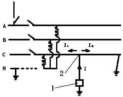
[0059] like figure 1 As shown, a ground fault occurs on the right side of the line in the figure, and it is only necessary to inject a detection signal I with a certain power at the detection point 2, (I=U÷Z, where U is the voltage applied to the detection point, and Z is the impedance of the wire ) I is divided into two branches I 1 and I 2 , a faulty I 2 Through the earth to form a loop, there is no fault I 1 Almost zero, there is a difference in the current on both sides, that is, I 2 >I 1 , so it can be judged that the fault range is in the I of detection point 2 2 side; at detection point 2 I 2 By using the method of the present invention to select detection points for detection again, the fault range can be narrowed down again, and the fault point can be found after repeated several times; if the detection is performed in groups, the detection efficiency will be further improved.

[0060] In addition, when a ground fault occurs, the ground at the fault point is n...

Embodiment 2

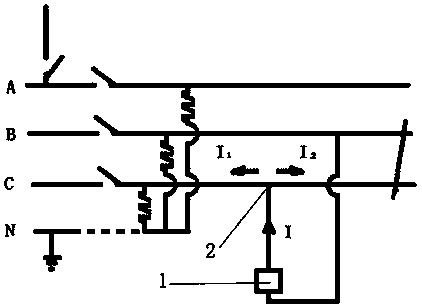
[0063] like figure 2 As shown, the bare conductor has a short-circuit fault between phases BC, the detection signal I is injected into the detection point 2 of phase C, and the ground terminal of the signal generator 1 is lapped to the conductor of phase B. Since there is a short-circuit point between the phases, a loop is formed, and I 2 > I 1 , it can be judged that the fault range is in I 2 side. This embodiment can also use Figure 10 -A structural form, the same effect can be achieved by lapping the B-phase conductor with a horizontal grounding rod (17).

[0064] According to the above method, the fault point can be found after repeated several times. Since the short-circuit circuit is not connected in series with an inductive load, this embodiment can use a DC detection signal or an AC detection signal.

[0065] For Embodiment 1 and Embodiment 2, the detection signal is any one or any combination of AC signals, DC signals, pulse signals, and different frequency sig...

Embodiment 3

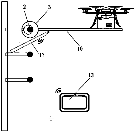
[0068] like Figure 3-4 As shown, a line fault detection device is mounted on an aircraft, which includes a detection module (3) and a signal module (16) with a signal generator (1), and the side of the signal module (16) is a detection module ( 3). The signal generator (1) and the signal module (16) can be arranged integrally or separately.

[0069] By remotely operating the UAV, the line fault detection device can be mounted on the power line for fault detection, especially suitable for scenarios where the road is blocked or the line is high from the ground, and the remote detection of power line faults is realized.

[0070] like Figure 8 As shown, preferably, the signal module (16) includes a first signal module (101) and a second signal module (102), and the first signal module (101) and the second signal module (102) are located in the detection module (3 ) on both sides. The first signal module and the second signal module successively input detection signals to the...


PUM


Abstract

The invention provides a line fault detection device mounted on an aircraft. The detection device comprises a detection module and a signal module with a signal generator. The signal generator inputsdetection signals into a detection point of a power line with a power failure fault successively or simultaneously; the detection module detects electric features of the two sides of the detection point to determine that a fault range is at a certain side of the detection point. When the detection device is in use, an unmanned aerial vehicle is remotely controlled to mount the circuit fault detection device on a power line so as to carry out fault detection. The circuit fault detection device is especially suitable for a road with block up or a line high above the ground; and remote detectionof the power line fault is realized.

Description

technical field [0001] The present invention relates to the technical field of line detection, and more specifically, to a line fault detection device. Background technique [0002] When a power line fails, the common method is: disconnect the section switch and branch line switch of the line, and then use the insulation resistance tester to perform section detection on the line; when the section line is long or there is no switch in this section, It is necessary to untie the wire barge interface for segment detection, so as to judge the fault range. Sometimes it is even necessary to untie the wire barge interface at multiple points for detection in order to determine the fault point. When looking for high-voltage line faults, the staff also have to work on the pole to untie the jumper on the pole. [0003] The detection steps of the above line fault detection method are cumbersome, the detection time is long, the detection efficiency is low, and the fault point cannot be ...

Claims


Application Information

Patent Timeline
Patent Type & Authority Applications(China)
IPC IPC(8): G01R31/08
CPCG01R31/085
Inventor 罗显泉
Owner 广东电网有限责任公司韶关供电局
Why Eureka
Try Eureka