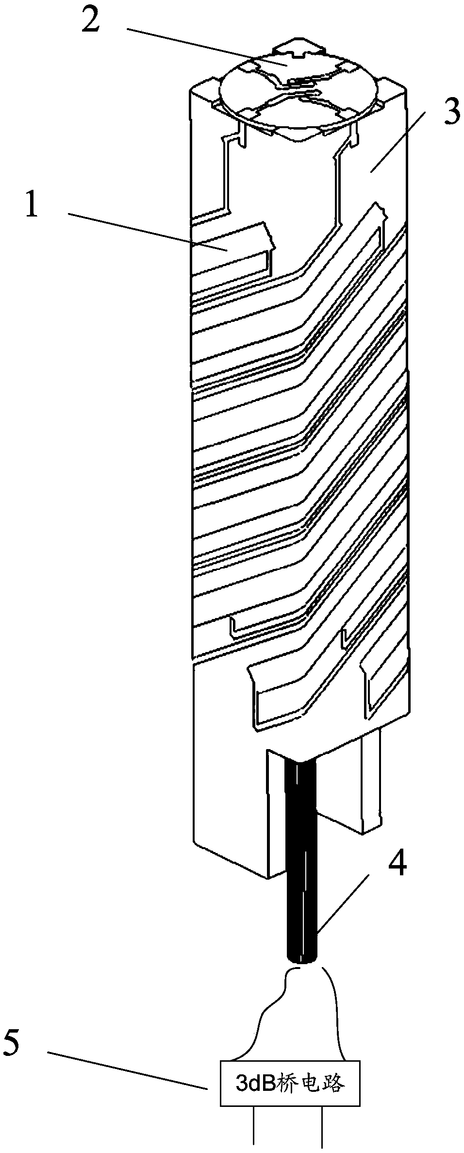
[0031] Such as figure 1 As shown, a new type of four-arm helical antenna includes a dual-frequency helical ribbon 1, a balun structure 2, a helical support medium 3, a cable 4, and an amplitude-phase output circuit 5. The input ends of the amplitude-phase output circuit 5 are respectively excited by the signal The port and the signal load port are connected, the output end is connected to one end of the cable 4, the cable 4 is arranged inside the spiral support medium 3, and passes through the spiral support medium along the center line of the spiral support medium 3. The balun structure 2 is set on the spiral support medium 3 At the top, the other end of the cable 4 is connected to the balun structure 2. The dual-frequency spiral belt 1 is arranged on the outer surface of the spiral support medium, and the balun structure 2 is connected to the dual-frequency spiral belt through the feed screw connection, and the antenna signal passes The signal excitation port is sent to the amplitude-phase output circuit 5, and then transmitted from the amplitude-phase output circuit 5 to the balun structure 2 through the cable 4, and then transmitted from the balun structure 2 to the dual-frequency spiral belt 1 through the feeding spiral node and sent out.
[0032] Wherein, the balun structure 2 includes a top disc 21, a crisscross microstrip plate 22, the dual-frequency spiral ribbon 1 is composed of spiral metal wires, and the balun structure 2 passes through the edge of the microstrip line of the crisscross microstrip board 22 The contact point is in contact with the spiral metal wire to connect the dual-frequency spiral belt 1.
[0033] In the new four-arm helical antenna provided by the present invention, a new power feeding method is adopted, and the dual-frequency helical ribbon structure is used as the antenna's radiator, which resonates in the transmitting and receiving frequency band by adjusting the length of the broken line section; and the balun structure is a parallel type Impedance converter, realizes two pairs of differential feeds to the four-arm helix, and uses 2 coaxial lines as external ports, so that the input impedance of the two input ports of the balun structure is half of the radiation impedance of the four-arm feed point ; The spiral support medium supports the dual-frequency spiral ribbon structure, and because of its dielectric characteristics, it realizes the miniaturization of the antenna; two equal-length thin cables provide the connection between the balun structure and the amplitude-phase output circuit, where the amplitude-phase output The circuit is a 3dB bridge circuit; and the 3dB bridge circuit realizes feeding the two coaxial input ports of the balun structure with equal amplitude and phase difference of ±90°, and then realizes the equal amplitude and phase of the four-arm helix with (0°, 90°, 180°, 270°) or (0°, -90°, -180°, -270°) distributed circular polarization excitation.
[0034] Such as Picture 9 As shown, the dual-frequency folded spiral belt structure 1 is composed of four identical spiral lines 11, 12, 13, and 14, which are arranged in rotation along the axial direction of the spiral support medium 3;
[0035] Such as Picture 10 As shown, the balun structure 2 is embedded in the top of the spiral support medium 3, and is connected to the four spiral lines 11, 12, 13, 14 with the edge of the disc microstrip line. The spiral support medium 3 provides attachment and support for the spiral belt structure 1 Generally, the spiral wires 11 are deposited on the four side metals of the spiral support medium 3 through the LDS process; and the two cables 4 are thin and flexible radio frequency cables that pass through the center of the spiral support medium 3. The lower square microstrip line of the Lun structure 2 is connected, and the other end is connected to the equal power division output port of the 3dB bridge circuit 5; the 3dB bridge circuit 5 is a stripline chip, as an accessory device of the antenna, achieving a constant amplitude phase difference of 90° The output of power points is generally integrated on the terminal circuit board.
[0036] Spiral 11 is a multi-folded spiral ribbon. By changing the width and length of each metal ribbon, the coupling relationship between the four identical spiral ribbon structures is changed to realize the impedance of the four-arm spiral antenna under differential feeding in the transceiver frequency band. match. The embedding of the helix 11 into the helical support medium 3 provides the possibility of resonating the dual-frequency helical band structure in the transmission and reception frequency band under the miniaturization of the structure size, thereby achieving antenna radiation. The U-shaped microstrip line circuit and the output microstrip line board in the cross microstrip board 22 use Rogers RT 6010 double-sided copper clad laminate with a thickness of 0.508mm, with a dielectric constant of 10.2, and the top disc 21 still uses a thickness of 0.60mm The PTFE double-sided copper clad laminate has a dielectric constant of 2.65. The spiral support medium 3 is a square hollow dielectric column, and uses a high dielectric constant LDS material (dielectric constant 4.35, dielectric loss tangent 0.005), which is convenient for mass production and manufacturing based on the LDS process. Two cables 41 and 42 extend downward along the central axis of the antenna, one end of which is connected to the output microstrip line of the balun structure, and the other end is connected to the two output ports of the 3dB bridge circuit 5.
[0037] Such as figure 2 As shown, the balun structure is used to carry out the differential feed of the four-arm spiral structure in two opposite directions, and the four-arm spiral structure is divided into two groups. Each set of spirals is composed of mutually opposed spirals, and the feed is equal in amplitude and 180 °, and these two sets of spirals respectively output one port, that is, if one of the ports is excited, the corresponding spiral set will be differentially fed. The equal amplitude 90° phase difference feed to the two ports will simultaneously excite the two sets of spirals to form a circularly polarized beam. In this way, in the antenna, a 3dB bridge circuit is used to realize the equal amplitude 90° phase difference feeding to the two sets of spirals in the four-arm spiral structure, and the new balun structure is used to realize the differential feeding to the two sets of spirals, achieving the four-arm spiral structure. Circular polarization four-point feed excitation with equal amplitude and phase of (0°, 90°, 180°, 270°) or (0°, -90°, -180°, -270°) distribution of arm helix purpose.
[0038] Such as image 3 As shown, the new balun structure adopted is composed of a double-sided U-shaped microstrip line and a four-point output microstrip line. The four-point output microstrip line is embodied as the edge contact point of the microstrip line in the balun structure. Connection relationship such as Figure 4 As shown, the U-shaped microstrip line is used to achieve a 180° phase shift in the working frequency band, and each group of spirals (spiral 1 and spiral 3, spiral 2 and spiral 4) are differentially fed.
[0039] Such as Figure 5 As shown, the spiral structure in the new four-arm spiral antenna consists of four identical spiral structures rotatingly arranged, and each spiral structure is formed by winding a (square) dielectric rod with a multi-folded spiral metal tape of different widths. The multi-folded structure Not only provides two resonance points for the four-arm spiral structure coupled with each other to cover the satellite communication transceiver frequency band, but also facilitates the miniaturization of the spiral structure and facilitates the integration on the entire terminal.
[0040] In this antenna, the direction of the main beam is changed by switching the excitation port, such as Image 6 Shown. When the signal excites port 1, the main beam direction is +Z axis direction, and when the signal excites port 2, the main beam direction is -Z axis direction, and its polarization characteristics are consistent, which meets the polarization judgment criterion When port 1 is excited by power, the phase distribution of the feed point of the four-arm spiral structure is (0°, 90°, 180°, 270°), and the corresponding unitary vector When port 2 is excited by power, the phase distribution of the feed point of the four-arm spiral structure is (0°, -90°, -180°, -270°), and the corresponding unitary vector and Therefore, when the direction of the main beam is switched, the polarization characteristic of the main beam remains unchanged.
[0041] In the application of the terminal, different main beam directions can be selected for satellite-to-satellite communication according to different positions or antenna directions of the terminal, such as Figure 7 As shown, when the terminal is used in an urban environment, the main beam direction switching function can be used to deal with the shielding effect of the building on the satellite-to-ground wireless link. The two-reflected wireless link is selected and the antenna is used as the main The beam is directed to the reverse beam for signal transmission and reception, such as Figure 8 Shown.
[0042] In the specific implementation, the characteristic impedance of the transmission line in the balun structure is set to 50 ohms, and the size of the four-arm spiral structure is adjusted to make it resonate at two frequencies, and the radiation impedance of the spiral structure feed point at the resonance point is 100 ohms, and Connect with the balun structure (2) with impedance parallel characteristics to realize the input impedance of the four-arm helical antenna radiator (including dual-frequency folded spiral ribbon structure 1, balun structure 2, spiral dielectric support 3, and two cables 4) It is 50 ohms, and the characteristic impedance of the transmission line in the cable 4, 3dB bridge circuit 5 is also selected to be 50 ohms. In this way, the entire antenna is matched with the terminal device to 50 ohms.
[0043] The content not described in detail in the specification of the present invention belongs to the well-known technology of those skilled in the art.