RJ connector assembling structure and assembling method thereof

A technology for assembling structures and connectors, which is applied in the assembly/disassembly and connection of parts and contacts of connection devices, and can solve problems such as increased production costs, cumbersome manufacturing processes, and complex mold structures.

Inactive Publication Date: 2018-03-23
文山意德电子科技有限公司
View PDF6 Cites 3 Cited by
  • Summary
  • Abstract
  • Description
  • Claims
  • Application Information

AI Technical Summary

Problems solved by technology

[0002] Existing RJ connectors include shells, RJ connector cores, RJ terminals, PIN terminals, PCB boards, and network filters. The RJ terminals and PIN terminals are usually molded integrally with the RJ connector cores by mosaic molding. As a result, the mold structure is complicated, the manufacturing process is cumbersome, the mold manufacturing cost is high, and it usually combines the RJ terminal, PIN terminal, and network filter through a PCB board, so that the RJ connector core and the PCB board are on the shell. The positioning structure of the shell becomes complicated, resulting in a complex mold structure for the production of the shell, increasing the overall production cost and reducing the processing efficiency

Method used


Image

  • RJ connector assembling structure and assembling method thereof
  • RJ connector assembling structure and assembling method thereof
  • RJ connector assembling structure and assembling method thereof

Examples


Embodiment Construction

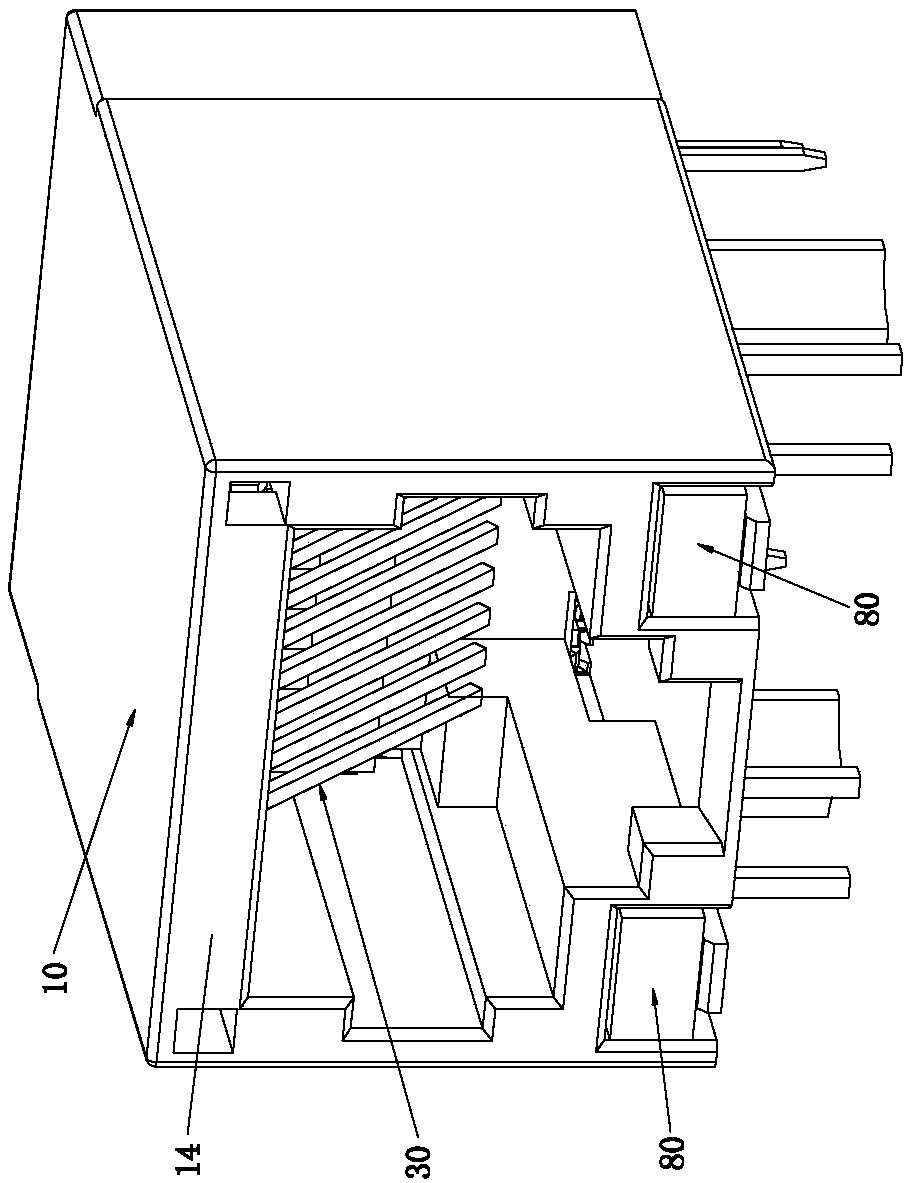
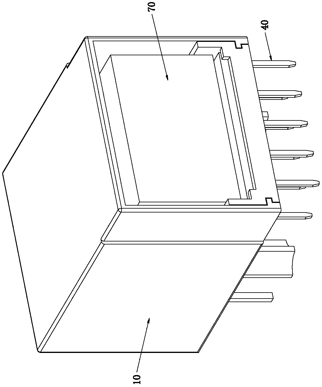
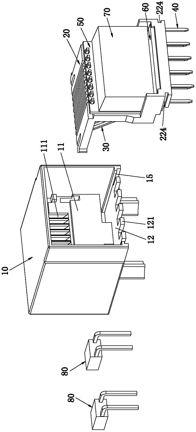
[0071] Please refer to Figure 1 to Figure 12 As shown, it shows the specific structure of the embodiment of the present invention; it includes: the shell 10 and the RJ connector ferrule 20 installed in the shell 10, the RJ terminal 30, the PIN terminal 40, the first PCB board 50, the second Two PCB board 60 , network filter 70 and indicator light 80 .

[0072] Specifically, the RJ connector ferrule 20 is inserted and installed in the housing cavity of the housing 10, the RJ terminal 30 and the PIN terminal 40 are installed on the upper and lower ends of the RJ connector ferrule 20 respectively, and the welding part of the RJ terminal 30 ( This article refers to the first welding part 33) passing through and connected to the upper end of the first PCB board 50, the first PCB board 50 is connected to the second PCB board 60, the welding part of the PIN terminal 40 (herein referred to as the second The welding part 41 ) is connected to the bottom of the second PCB 60 , the netw...


PUM


Abstract

The invention discloses an RJ connector assembling structure and an assembling method thereof. The RJ connector assembling structure comprises a housing, an RJ connector insertion core, an RJ terminal, a PIN terminal, a first PCB, a second PCB, a network filter and an indicating lamp, wherein the RJ connector insertion core, the RJ terminal, the PIN terminal, the first PCB, the second PCB, the network filter and the indicating lamp are mounted in the housing. The RJ connector insertion core is inserted into an accommodating chamber which is mounted on the housing. The RJ terminal and the PIN terminal are respectively mounted at the upper end and the lower end of the RJ connector insertion core. The welding part of the RJ terminal is connected with the upper end of the first PCB. The firstPCB is connected with the second PCB. The welding part of the PIN terminal is connected with the second PCB. The network filter is inserted into and mounted on the first PCB. The indicating lamp is inserted into and mounted in the housing. Therefore the RJ terminal is connected with the PIN terminal through the first PCB and the second PCB, and positioning structures of the RJ connector insertioncore and the PCBs on the housing are simplified. The RJ connector assembling structure and the assembling method thereof have advantages of realizing ingenious and reasonable structure design and easyforming and manufacture, simplifying the positioning structure of each component and a forming and manufacturing mold, reducing production cost and improving machining efficiency.

Description

technical field [0001] The invention relates to the technology in the field of connectors, in particular to an assembly structure and an assembly method of an RJ connector. Background technique [0002] Existing RJ connectors include shells, RJ connector cores, RJ terminals, PIN terminals, PCB boards, and network filters. The RJ terminals and PIN terminals are usually molded integrally with the RJ connector cores by mosaic molding. As a result, the mold structure is complicated, the manufacturing process is cumbersome, the mold manufacturing cost is high, and it usually combines the RJ terminal, PIN terminal, and network filter through a PCB board, so that the RJ connector core and the PCB board are on the shell. The positioning structure of the housing becomes complicated, resulting in a complex mold structure for making the shell, increasing the overall production cost and reducing the processing efficiency. [0003] Therefore, a new technology needs to be developed to so...

Claims


Application Information

Patent Timeline
Patent Type & Authority Applications(China)
IPC IPC(8): H01R13/11H01R13/502H01R13/66H01R43/20
Inventor 游保林
Owner 文山意德电子科技有限公司
Why Eureka
Try Eureka