
Indexable milling cutter blade and milling cutter

A technology of milling inserts and inserts, which is applied in the field of indexable circular milling inserts and milling tools, can solve the problems of affecting cutting performance, insufficient chip space, high manufacturing cost, etc., and achieves convenient operation, accurate positioning, and simplified positioning structure Effect

Active Publication Date: 2013-03-13
株洲欧科亿切削工具有限公司
View PDF8 Cites 3 Cited by
  • Summary
  • Abstract
  • Description
  • Claims
  • Application Information

AI Technical Summary

Problems solved by technology

Chinese patent CN1018111203A discloses a circular milling insert. The circular milling insert disclosed in the above-mentioned patent is for effective positioning. In addition to the positioning surface obtained by cutting the lower section of the conical surface, the upper surface is also provided with a number and The grooves equal to the cutting unit are used for the turning and positioning of the blades to ensure the positioning effect. In actual processing, the pressing device needs to cooperate with the grooves, which will lead to insufficient chip space in semi-finishing and rough machining, affecting Cutting performance, and complex structure, high manufacturing cost

Method used


Image

  • Indexable milling cutter blade and milling cutter
  • Indexable milling cutter blade and milling cutter
  • Indexable milling cutter blade and milling cutter

Examples


Embodiment 1

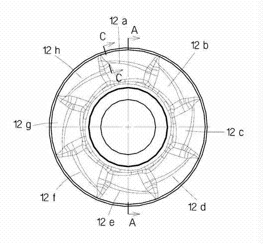
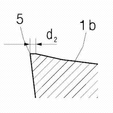
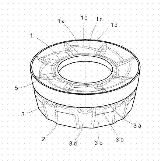
[0043] An indexable circular milling insert, as attached Figure 1-6 As shown, the blade body is conical, including an upper surface 1, a lower surface 2, and a side surface 3 connecting the upper surface and the lower surface. The geometric center of the blade body is provided with a blade positioning hole. The side surface 3 includes a flank surface 3a close to the upper surface 1 and a positioning surface close to the lower surface 2, a groove is arranged between the positioning surface and the flank surface 3a, and a plurality of uniform grooves are arranged on the positioning surface. Distributed positioning platform 13. The positioning platform 13 includes a positioning plane 3c protruding outward from the side surface 3 and a transition surface 3b connecting the groove and the positioning plane 3c, the positioning plane 3c extends from the transition surface 3b to the lower surface 2, and the lower Surface 2 is the reference plane for blade installation.

[0044] For ...


PUM


Abstract

The invention discloses an indexable milling cutter blade and a milling cutter. A cutter blade body is in the shape of a cone and comprises an upper surface, a lower surface and a side surface connecting the upper surface with the lower surface. The geometric center of the cutter blade body is provided with a cutter blade positioning hole. The side surface comprises a rear cutter surface near the upper surface, and a positioning surface near the lower surface; a groove is arranged between the positioning surface and the rear cutter surface; the positioning surface is provided with a plurality of positioning tables which are distributed uniformly; each positioning table comprises a positioning plane protruding outwards from the side surface, and a transition surface for connecting the groove with the positioning plane; each positioning plane extends to the lower surface from the transition surface; and the lower surface 2 is a cutter blade installation reference plane. Each protruding positioning plane clings to a positioning side surface of a cutter groove to restrict the radial rotation of the blade, then the rear cutter surface of the blade clings to the positioning side surface of the cutter groove, therefore the blade is positioned correctly and prevented from rotating and sliding under the actions of cutting force and friction force in processing.

Description

technical field [0001] The invention relates to a metal cutting blade and a cutting tool, in particular to an indexable circular milling blade and a milling tool capable of realizing accurate positioning. Background technique [0002] Indexable circular milling inserts and milling tools are commonly used metal cutting tools. During the processing and use of circular milling inserts, only a part of the cutting edge of the cutting insert participates in cutting. In this process, the cutting edge of the cutting workpiece The length will vary with the depth of cut. When the cutting edge involved in cutting wears to a predetermined level, a new cutting edge needs to be rotated to the processing position. Therefore, the rotation positioning of the indexable circular milling insert is required to be fast and simple. The positioning structure of the circular milling blade in the prior art is generally to lock the circular milling blade in the groove by passing the screw through the...

Claims


Application Information

Patent Timeline
Patent Type & Authority Applications(China)
IPC IPC(8): B23C5/02B23C5/08
Inventor 李树强邓剑袁美和谭文清黄立尹江华
Owner 株洲欧科亿切削工具有限公司
Learn More