Swing bar type automatic glaze dipping device

An automatic and glaze-dipping technology, which is applied in the field of daily-use ceramic production equipment, can solve the problems of inconsistent glaze layer thickness, unqualified body glaze, insufficient automation, etc., to achieve no dead angle glaze, good glaze effect, Easy to control effects

Active Publication Date: 2015-12-23
XUZHOU XINLONG PIPE IND CO LTD
View PDF8 Cites 0 Cited by
  • Summary
  • Abstract
  • Description
  • Claims
  • Application Information

AI Technical Summary

Problems solved by technology

This device is suitable for the glazing process of ceramic tiles, but it has very strict requirements on the rheological dynamic parameters of the glaze water. If the glaze water changes or the composition of the glaze water is not uniform enough, it will easily cause the thickness of the glaze layer to be inconsistent, which will directly affect the yield.
[0009] 6. Patent document [publication number is CN203187583U] In the utility device patent titled "automatic glazing device for daily-use ceramics", there are glaze suction holes on the wall of the glaze storage cylinder, so that the glaze water can be sucked into the glaze storage cylinder to be glazed on the bottom of the bowl In the production process, it was found that when the suction cup mechanism sucks the bowl body and swings to the glaze pool for glazing, the time for the bottom of the bowl to contact the glaze water is relatively longer than the time for the bowl surface to contact the glaze water. For some bodies with strong water absorption, use this If the glaze layer is glazed by a different method, the thickness of the glaze layer at the bottom of the bowl is obviously greater than that on the surface of the bowl, and the glaze on the green body is unqualified.
[0010] In summary, the existing glazing devices mainly have defects such as low efficiency, poor glazing quality, complex structure, excessive labor intensity of workers, and insufficient automation

Method used


Image

  • Swing bar type automatic glaze dipping device
  • Swing bar type automatic glaze dipping device
  • Swing bar type automatic glaze dipping device

Examples


Embodiment Construction

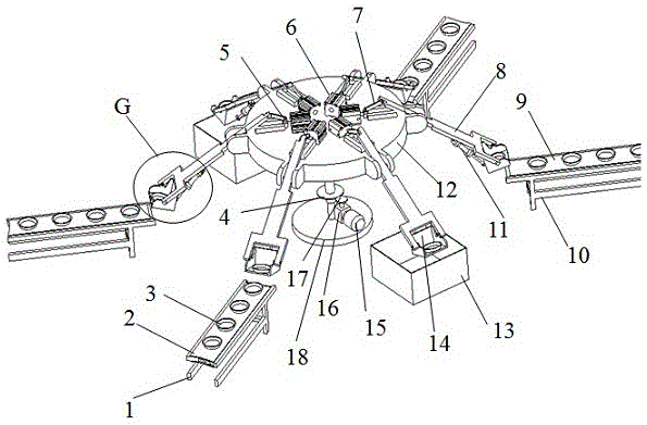
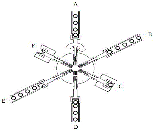
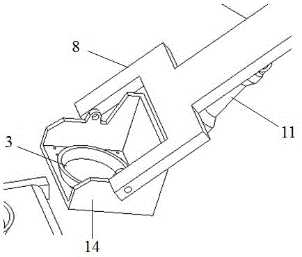
[0026] Such as Figure 1-3 As shown, the turntable motor 15 drives the sheave puller 17 to rotate through the reducer 16, and the sheave puller 17 moves the sheave 4 to rotate at intervals. At the same time, the swing angle cylinder 6 pulls the slider 5 along the radius of the turntable 12 Direction moves, and the tilting plate 8 elevation angle increases pallet 14 to the position equal to conveyor belt 2 9, at B, E station, the conveyor belt 2 9 that is installed on the transmission support 2 10 pushes the bowl base 3 into the tray 14 Bottom, then the tilting cylinder 11 pushes the tray 14 to rotate an angle around the hinge center with the tilting plate 8, and the bowl base 3 slides down to the inner right angle of the tray 14 to complete the preparatory work before glazing.

[0027] Then the turntable motor 15 drives the sheave puller 17 to rotate, the turntable 12 is indexed one-sixth of a week to the C and F stations, the tray 14 and the bowl blank 3 to be glazed move to ...


PUM


Abstract

The invention provides an automatic oscillating bar type glazing device. A conveyor belt is used for conveying a to-be-glazed bowel billet to a conveying support, a tilt angle cylinder piston rod retracts to pull a sliding block to the center of a rotary table, the sliding block enables an inclined plate to rotate around a hinged center of the sliding block and the rotary table by virtue of a push-pull rod, a tilting cylinder enables the bottom surface of a tray to be parallel to the top surface of a conveying support II, the bowel billet enters into the tray after being pushed by a conveyor belt II, then the tilting cylinder acts again to tilt the tray, the bowel billet can not slide out from the tray, a rotary table motor drives the rotary table to stations C and F, the tilt angle cylinder piston rod extends out to immerse the bowel billet and the tray into a glaze tank, so as to be glazed, then the rotary table rotates to stations A and D, the tilting cylinder enables the tray to tilt, and the bowel billet slides onto a conveyor belt I along the tray, so that a glazing process is completed. The automatic oscillating bar type glazing device can be used for an automatic glazing technology in a daily ceramic production process, and the defects of a traditional glazing device that a driving mechanism is complex, glazing quality is poor and automation degree is low are overcome.

Description

technical field [0001] The invention relates to daily-use ceramic production equipment, in particular to an automatic glazing device used in the production process of daily-use ceramics. Background technique [0002] In the production of daily-use ceramics in the past, due to the difference in the performance of raw materials or the limitation of the shape of various products, the glazing process of various ceramic manufacturers can only be performed by manual glazing. The production efficiency of manual glazing is low. During the glazing process, fingers touch the green body, leaving fingerprints on the green body after glazing, which affects the glazing quality of the green body. In addition, since there are various chemical materials added to the glaze water, these chemical materials have a corrosive effect on the human body, and long-term manual glazing is harmful to the human body. [0003] In order to improve production efficiency, improve product quality, improve the...

Claims


Application Information

Patent Timeline
Patent Type & Authority Patents(China)
IPC IPC(8): C04B41/86
Inventor 梁康宁陈华东吕昌保
Owner XUZHOU XINLONG PIPE IND CO LTD
Why Eureka
Try Eureka