Skin medicine-applying device for surgery department

A skin and drug application technology, applied in the field of medical devices, can solve the problems of large waste, low sanitation, low efficiency, etc., and achieve the effects of high efficiency, convenient use and ingenious structure

Inactive Publication Date: 2018-03-27
HEBI CITY PEOPLES HOSPITAL
6 Cites 24 Cited by

AI-Extracted Technical Summary

Problems solved by technology

[0005] In view of the above situation, in order to overcome the defects of the prior art, the present invention provides a surgical skin dru...

Method used

1, clean and hygienic, save medicinal liquid; The present invention abandons the method that traditional drug applicator uses the absorbent material such as sponge to carry out drug application, by designing liquid outlet pipe 7, liquid outlet head 8 and ball 10, by outlet The cooperation of the liquid tube 7 and the liquid outlet head 8 enables the liquid medicine to be automatically coated on the patient's body surface with the rotation of the ball 10; compared with the traditional sponge and other materials, the ball 10 is not absorbent, so the liquid medicine will not be absorbed It causes waste in the material, and at the same time avoids the hygienic and safety hazards caused by the adsorption material that is not easy to clean after absorbing the liquid medicine, and is easy to be contaminated with accumulated dust; in addition, materials such as sponges are often loose and porous, and bacteria and impurities can easily penetrate into the device. Contaminate the liquid medicine, and after the device is used, the liquid outlet head 8 is pressed down under the pressure of the piston 13, the conical surface of the liquid outlet head 8 and the conical surface of the liquid outlet pipe 7 are pressed tightly, and the first through hole 9 is closed. The sealing effect is good, and the infection of dust and bacteria is eliminated.
2, during drug application, the thickness of the drug layer is adjustable and controllable; this device can adjust the pre-tightening force of the stage clip 14 by the screw mandrel 16, thereby adjusting the pressure of the piston 13 to the liquid medicine in the isolation cavity 4, thereby controlling the first When the through hole 9 is opened, the liquid discharge speed of the medicinal liquid can adjust the thickness of the applied medicinal layer according to the needs of the affected part, so that the dosage of the medicinal preparation is more reasonable.
4, the present invention can be used for each position to apply medicine conveniently; Liquid outlet pipe 7 of the present invention can slide along the second through hole 20, thereby can realize that liquid outlet pipe 7 retracts in the second through hole 20, makes A plurality of liquid outlet pipes 7 can adapt to the application of medicine on uneven parts such as elbows, knees and ank...

Abstract

The invention relates to a skin medicine-applying device for the surgery department. Therefore, problems of a conventional medicine-applying method such as poor efficiency, great waste and low cleanness are effectively resolved. In order to the resolve the above problems, the technical scheme is characterized in that the device comprises a housing; the housing is divided into a medicine liquid cavity and a separation cavity; a liquid inlet pipe is connected between the medicine liquid cavity and the separation cavity; the bottom of the separation cavity is equipped with multiple liquid outletpipes which is internally provided with liquid outlet heads; conical surfaces of the liquid outlet heads are matched with conical surfaces of the liquid outlet pipes; the upper ends of the liquid outlet heads are sealed; the conical surfaces of the liquid outlet heads are equipped with first through holes; the lower ends of the liquid outlet heads are equipped with rolling balls; spherical surfaces of the rolling balls are equipped with grooves; a piston is installed in the separation cavity; a pressure spring is arranged above the piston; the upper end of the pressure spring is equipped witha pressing board; the upper surface of the pressing board is connected with a screw rod; a fixed nut sleeves the rod; a separation sleeve sleeving outside the pressure spring is installed in the medicine liquid cavity; and the upper surface of the piston is fixedly connected with a vertical pull rod; the upper end of the pull rod penetrates through the pressure spring, the pressing board and the screw rod and extends out of the housing. The skin medicine-applying device for the surgery department is novel in concept and indigenous in structure.

Application Domain

Technology Topic

PistonSurgery procedure +3

Image

  • Skin medicine-applying device for surgery department
  • Skin medicine-applying device for surgery department
  • Skin medicine-applying device for surgery department

Examples

  • Experimental program(1)

Example Embodiment

[0014] The specific embodiments of the present invention will be described in further detail below in conjunction with the accompanying drawings.
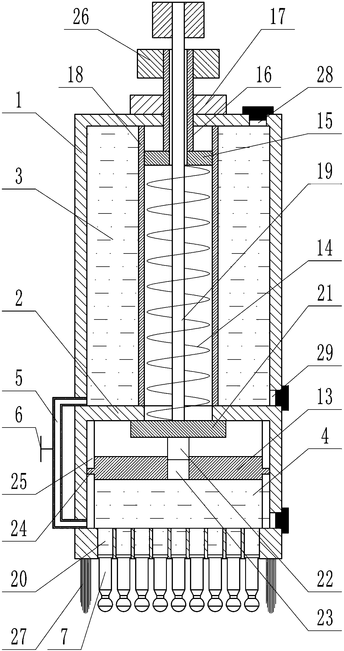
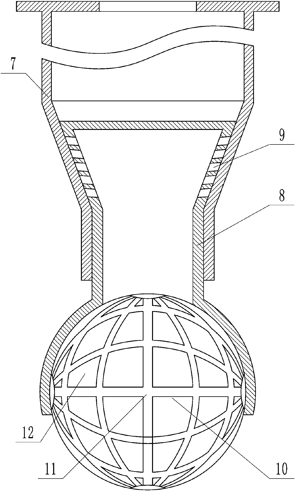
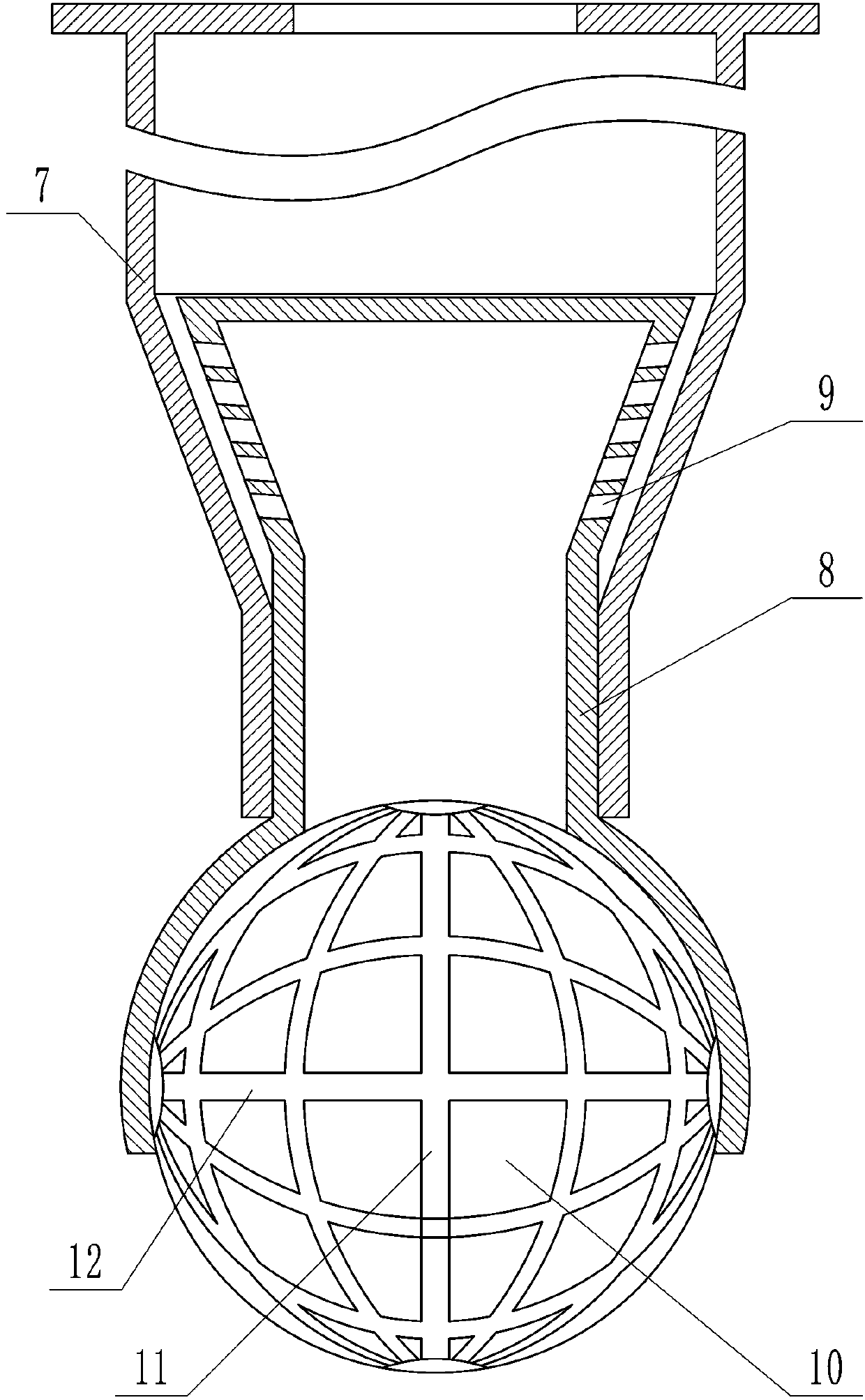
[0015] by Figure 1 to Figure 6 Given that the present invention includes a housing 1, a horizontal partition 2 is provided in the housing 1, and the horizontal partition 2 divides the housing 1 into an upper liquid medicine cavity 3 and a lower isolation cavity 4, the bottom of the liquid medicine cavity 3 and A liquid inlet pipe 5 is connected to the bottom of the isolation cavity 4, a switch valve 6 is arranged on the liquid inlet pipe 5, a plurality of liquid outlet pipes 7 are installed at the bottom of the isolation cavity 4, the lower end of the liquid outlet pipe 7 is located outside the housing 1, and the liquid outlet pipe 7 The lower end is a tapered tube with a small end facing downwards. Each outlet pipe 7 is equipped with a liquid outlet head 8. The liquid outlet head 8 can slide up and down in the liquid outlet pipe 7, and the upper end of the liquid outlet head 8 has a small end facing down The taper tube is placed in the outlet pipe 7 and matched with the taper pipe at the lower end of the outlet pipe 7, the upper end of the outlet head 8 is closed and the taper surface is provided with a plurality of transverse first through holes 9, the outlet head 8 taper pipe The lower end of the vertical pipe is connected with a vertical pipe, and the lower end of the vertical pipe extends out of the lower nozzle of the outlet pipe 7 and is slidably fitted with the lower nozzle of the outlet pipe 7. A ball 10 is installed at the lower end of the vertical pipe, and there are multiple warp threads on the spherical surface of the ball 10 Groove 11 and a plurality of weft grooves 12; a piston 13 that can slide up and down is installed in the isolation chamber 4. A compression spring 14 is installed above the piston 13. The lower end of the compression spring 14 contacts the upper surface of the piston 13, and the upper end extends through the horizontal partition 2 The upper end of the compression spring 14 is in contact with the lower surface of the pressure plate 15, and the upper surface of the pressure plate 15 is fixedly connected with a vertical screw 16, and the upper end of the screw 16 extends out of the liquid medicine cavity 3. , The screw 16 is covered with a fixed nut 17, and the liquid medicine chamber 3 is equipped with an isolation sleeve 18 sleeved outside the compression spring 14; the upper surface of the piston 13 is fixedly connected with a vertical pull rod 19, and the upper end of the pull rod 19 passes through the compression spring 14. The pressing plate 15 and the screw rod 16 extend out of the housing 1.
[0016] In order to make the present invention more convenient to use when applying medicine to non-flat areas such as elbows, knees, ankles, etc., the bottom of the isolation tank is provided with a plurality of vertical second through holes 20, and a plurality of liquid outlet pipes 7 one One correspondingly installed in the plurality of second through holes 20, the liquid outlet tube 7 and the second through holes 20 are attached and can slide along the second through holes 20 without being separated.
[0017] In order to enable the present invention to adjust the amount of liquid medicine in the isolation tank according to the required amount of medicine to avoid waste, a baffle 21 is provided above the piston 13 and a vertically installed bolt 22 is connected to the center of the lower surface of the baffle 21. The center of the piston 13 is provided with a vertical threaded hole 23, the lower end of the bolt 22 is screwed into the threaded hole 23, a slider 24 is provided on the circumferential surface of the piston 13, a vertical groove 25 is provided on the side wall of the isolation chamber 4, and the slider 24 is placed The lower end of the compression spring 14 is in contact with the upper surface of the baffle 21, and the lower end of the pull rod 19 is fixedly connected to the baffle 21.
[0018] In order to rotate the pull rod 19 and the screw 16 more conveniently, the upper ends of the pull rod 19 and the screw 16 are provided with a knob 26.
[0019] In order to realize the rotating installation of the ball 10 at the lower end of the liquid outlet pipe 7, the lower end of the liquid outlet pipe 7 is a spherical shell-shaped holding tile structure with a lower opening. The ball 10 is placed in the holding shoe, and the outer wall of the ball 10 and the inner wall of the holding shoe rotate Together.
[0020] In order to make the coating of the liquid medicine more uniform, a circle of vertical bristles 27 is installed on the bottom surface of the casing 1, and a circle of bristles 27 surrounds a plurality of liquid outlet pipes 7.
[0021] A liquid inlet 28 is opened on the upper part of the liquid medicine cavity 3, and a liquid discharge opening 29 is opened on the bottom of the liquid medicine cavity 3 and the isolation cavity 4.
[0022] In order to realize the non-disengagement and sliding installation of the liquid outlet pipe 7 in the second through hole 20, the lower end of the second through hole 20 is necked, and the upper end of the liquid outlet pipe 7 is provided with a lower orifice with a diameter larger than that of the second through hole 20 The shaft shoulder, the shaft shoulder and the large diameter part of the second through hole 20 are slidingly fitted.
[0023] When the present invention is specifically used, the liquid inlet hole on the liquid medicine tank is first opened, the liquid medicine is added to the liquid medicine tank, and then the piston 13 is pulled upward through the pull rod 19 until the baffle plate 21 contacts the horizontal partition plate 2, and the piston Pull 13 to the uppermost position, and then open the on-off valve 6 on the liquid inlet pipe 5; when the piston 13 moves upward, a negative pressure is formed in the isolation chamber 4 below the piston 13, under the action of this negative pressure and the weight of the liquid medicine , The liquid medicine in the liquid medicine tank flows into the isolation cavity 4 through the liquid inlet pipe 5. After the isolation tank is filled with liquid medicine, the switch valve 6 is closed, the pull rod 19 is released, and the pressure of the compression spring 14 acts on the medicine through the piston 13 On the liquid, the pressure of the compression spring 14 is greater than the pressure of the gas in the airbag. The liquid medicine enters the liquid outlet tube 7 under the pressure of the piston 13, and the liquid outlet tube 7 pops out of the second through hole 20 under the action of the liquid pressure. 8 Press down under the action of its own weight and liquid pressure, so that the inner cone surface of the liquid outlet pipe 7 and the outer cone surface of the liquid outlet head 8 are closely attached, the first through hole 9 is closed, and the liquid medicine cannot enter the liquid outlet head 8. ; A part of the liquid medicine is isolated in the isolation cavity 4 for application, so that most of the liquid medicine does not come into contact with the ball 10, so that the ball 10 is not contaminated with bacteria or other impurities on the patient's body surface or outside to contaminate the remaining liquid medicine.
[0024] After the above process is completed, the device can be used to apply the medicine. The applicator holds the tool to make the lower part of the ball 10 contact with the patient’s body surface and press it down slightly, so that the liquid ejection head 8 overcomes the liquid pressure at its upper end. Move upward, the inner cone surface of the liquid outlet pipe 7 and the outer cone surface of the liquid outlet head 8 no longer fit, the first through hole 9 is opened, and the liquid medicine enters through the first through hole 9 under the pressure of the piston 13 and its own weight The liquid outlet head 8 is then pushed to make the ball 10 roll on the patient's body surface. During the rolling process of the ball 10, the liquid medicine in the liquid outlet head 8 passes through the multiple warp grooves 11 and The weft groove 12 flows to the outside of the liquid outlet 8 and is coated on the patient's skin by the ball 10, and then the bristles 27 evenly sweep the liquid medicine on the affected area; as the liquid medicine in the isolation cavity 4 continues to decrease, the piston 13 is pressing The downward movement of the spring 14 continues to pressurize the liquid medicine. During the downward pressing of the piston 13, the stroke of the piston 13 is small relative to the length of the compression spring 14, so the change in the elastic force of the compression spring 14 caused by the movement of the piston 13 can be ignored; During the application process, the liquid outlet tube 7 can automatically adjust the length of the retracted into the second through hole 20 according to the undulation of the application site, so as to automatically adapt to the shape of the application site, so that the balls on the multiple liquid outlet pipes 7 10 can effectively contact the affected area and improve the effect of application.
[0025] The present invention can adjust the thickness of the medicine layer when applying the medicine by adjusting the screw rod 16. When the required medicine layer is thin, the screw rod 16 is rotated counterclockwise through the knob 26 on the screw rod 16 to drive the pressing plate 15 to move upward. , The pre-tightening force of the compression spring 14 is reduced, and the pressure of the compression spring 14 on the piston 13 is also reduced, so that the pressure of the liquid medicine in the isolation chamber 4 is reduced, and the liquid discharge speed becomes slow when the first through hole 9 is opened. , The drug layer applied on the patient's body surface is thin; on the contrary, if the drug layer to be coated is thicker, the screw 16 is driven to rotate clockwise through the knob 26, so that the pressure plate 15 is lowered, and the pre-tightening force of the compression spring 14 is increased. Larger, the pressure of the piston 13 on the liquid medicine in the isolation chamber 4 increases, the liquid discharge speed becomes faster when the first through hole 9 is opened, and the medicine layer applied on the patient's body surface becomes thicker.
[0026] The present invention can also adjust the amount of liquid medicine that enters the isolation cavity 4 each time the medicine is applied according to the size of the medicine application area. If the medicine liquid required for this application is less, the knob 26 on the pull rod 19 is turned to make the pull rod 19 rotates counterclockwise, the tie rod 19 drives the baffle 21 at its lower end and the bolt 22 under the baffle 21 to rotate counterclockwise. Since the slider 24 on the piston 13 is clamped in the vertical groove 25 on the side wall of the isolation tank, the piston 13 cannot Rotation, so when the bolt 22 rotates counterclockwise in the threaded hole 23, it will move upward to drive the baffle 21 upward, that is, the distance between the piston 13 and the baffle 21 increases, when the baffle 21 is pulled to contact with the horizontal baffle 2 That is, when the piston 13 is pulled to the uppermost position, the position of the piston 13 is lower than before adjustment, so the space of the isolation chamber 4 below the piston 13 is reduced, and the amount of liquid medicine entering decreases, that is, the liquid medicine used for this application is reduced; If there is more liquid medicine needed for this application, turn the knob 26 on the pull rod 19 to make the pull rod 19 rotate clockwise, and the pull rod 19 drives the baffle 21 at its lower end and the bolt 22 under the baffle 21 in a smooth manner. Turn clockwise, when the bolt 22 rotates clockwise in the threaded hole 23, it will move downward to drive the baffle 21 downward, that is, the distance between the piston 13 and the baffle 21 is reduced, when the baffle 21 is pulled to the horizontal baffle 2 When the piston 13 is pulled to the uppermost position, the position of the piston 13 is higher than before adjustment, so the space of the isolation chamber 4 under the piston 13 increases, and the amount of liquid medicine entering increases, that is, the liquid medicine used for this application increases ; Through adjustment, the amount of liquid medicine isolated each time can be matched with the amount of liquid medicine required to avoid waste of liquid medicine.
[0027] If it is necessary to replace the liquid medicine in the liquid medicine tank, open the liquid discharge port 29 on the liquid medicine tank, drain the liquid medicine in it, and add new liquid medicine after cleaning the liquid medicine tank; If the liquid medicine is not used up, open the drain port 29 on the isolation tank and drain the remaining liquid medicine.
[0028] The present invention has the following remarkable advantages:
[0029] 1. Clean and hygienic, save liquid medicine; the present invention abandons the traditional method of applying sponge and other absorbent materials for the medicine application device, by designing the liquid outlet pipe 7, the liquid outlet head 8 and the rolling ball 10, through the liquid outlet pipe 7 Cooperating with the liquid ejection head 8, the liquid medicine is automatically coated on the patient's body surface with the rotation of the ball 10; compared to the traditional sponge and other materials, the ball 10 is not absorbent, so it will not cause the liquid medicine to be absorbed in the material It causes waste, and also avoids the hygienic safety hazards caused by the adsorptive materials that are difficult to clean after absorbing the liquid, and it is easy to be contaminated with accumulated dust; in addition, materials such as sponges are often loose and porous, and bacteria and impurities can easily penetrate into the device to contaminate the liquid. , And after the device is used, the liquid outlet head 8 is pressed down under the pressure of the piston 13, the cone surface of the liquid outlet head 8 and the cone surface of the liquid outlet pipe 7 are compressed, the first through hole 9 is closed, and the sealing effect is good , Put an end to the infection of dust and bacteria.
[0030] 2. The thickness of the medicine layer is adjustable and controllable when applying medicine; this device can adjust the pre-tightening force of the compression spring 14 through the screw 16 to adjust the pressure of the piston 13 against the liquid medicine in the isolation chamber 4, thereby controlling the first through hole 9 When the medicine is opened, the liquid discharge speed can be adjusted according to the needs of the affected area to adjust the thickness of the applied medicine layer to make the amount of medicine more reasonable.
[0031] 3. The remaining liquid medicine in the device is not contaminated; this device is equipped with an isolation cavity 4 below the liquid medicine cavity 3. Each time a medicine is applied, a part of the liquid medicine is isolated from the medicine industry cavity and enters the isolation cavity 4. The isolation cavity The liquid medicine in 4 is used for application, and the liquid medicine in the remaining liquid medicine cavity 3 is not in contact with the ball 10, which prevents bacteria and impurities on the patient's surface or outside from being brought into the liquid medicine by the ball 10 during the rolling process Causes the contamination of the liquid medicine, so that the liquid medicine in the liquid medicine cavity 3 can be stored safely for a long time; in addition, the present invention designs a baffle 21 that is connected to the piston 13 through a thread, and the baffle 21 and the piston 13 can be precisely adjusted by the thread. Therefore, the volume of the isolation cavity 4 under the piston 13 can be adjusted to control the amount of liquid in the isolation cavity 4 each time.
[0032] 4. The present invention can be conveniently applied to various parts; the liquid outlet tube 7 of the present invention can slide along the second through hole 20, so that the liquid outlet tube 7 can be retracted into the second through hole 20 to make multiple outlets The liquid tube 7 can be adapted to the application of uneven parts such as elbows, knees and ankles, which is more convenient and effective to use.
[0033] The invention has novel conception, clever structure, clean and hygienic use, convenient use, good coating effect and high efficiency.

PUM

no PUM

Description & Claims & Application Information

We can also present the details of the Description, Claims and Application information to help users get a comprehensive understanding of the technical details of the patent, such as background art, summary of invention, brief description of drawings, description of embodiments, and other original content. On the other hand, users can also determine the specific scope of protection of the technology through the list of claims; as well as understand the changes in the life cycle of the technology with the presentation of the patent timeline. Login to view more.

Similar technology patents

Method for deodorizing garbage by utilizing composite microbial agent

Owner:GUANGXI HONGSHENGYUAN ENVIRONMENTAL PROTECTION CO LTD

Classification and recommendation of technical efficacy words

  • Novel idea
  • Ingenious structure

Method for preparing natural nontoxic adhesive for wood use

Owner:武汉正轩宇生物科技有限公司

Oil spilling alarm buoy device

Owner:北京奥佳科技发展有限公司

Light source capable of supplying polychromatic light and method thereof

ActiveCN101592308AEliminate spoke flareIngenious structureElectric lightingPicture reproducersSpokeLight beam
Owner:APPOTRONICS CORP LTD
Why Eureka
Try Eureka