
Swivel arrangement for carousel filler

A technology of rotary device and filler, which is applied in packaging, liquid bottling, transportation and packaging, etc., and can solve problems such as the speed limitation of rotary tank and rotary transfer filler

Inactive Publication Date: 2018-03-27
TETRA LAVAL HLDG & FINANCE SA
View PDF4 Cites 0 Cited by
  • Summary
  • Abstract
  • Description
  • Claims
  • Application Information

AI Technical Summary

Problems solved by technology

In addition, due to the aforementioned considerations of maintaining a sterile environment, the rotational speed of rotary tanks and rotary transfer fillers is limited, as components that are heavily loaded, such as bearings and bushings, fail at an unacceptable frequency

Method used


Image

  • Swivel arrangement for carousel filler
  • Swivel arrangement for carousel filler
  • Swivel arrangement for carousel filler

Examples


Embodiment Construction

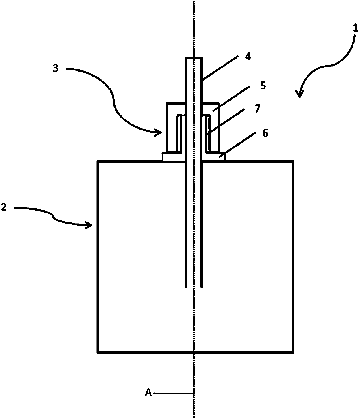
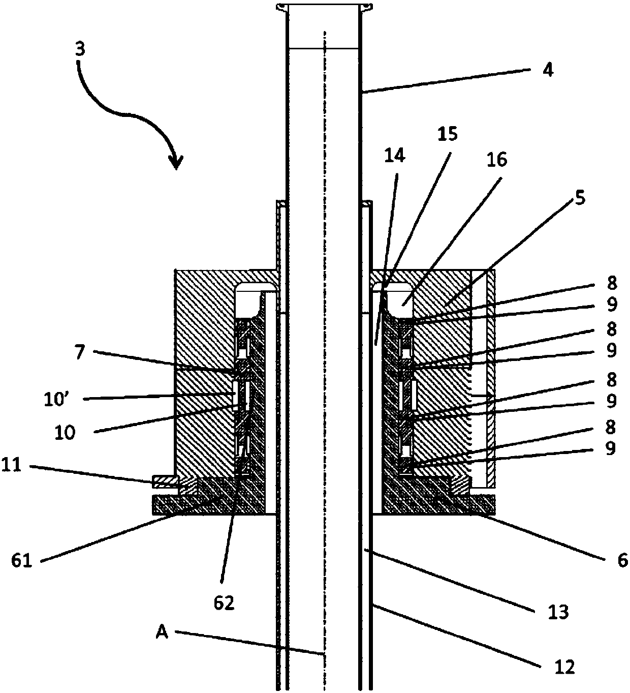
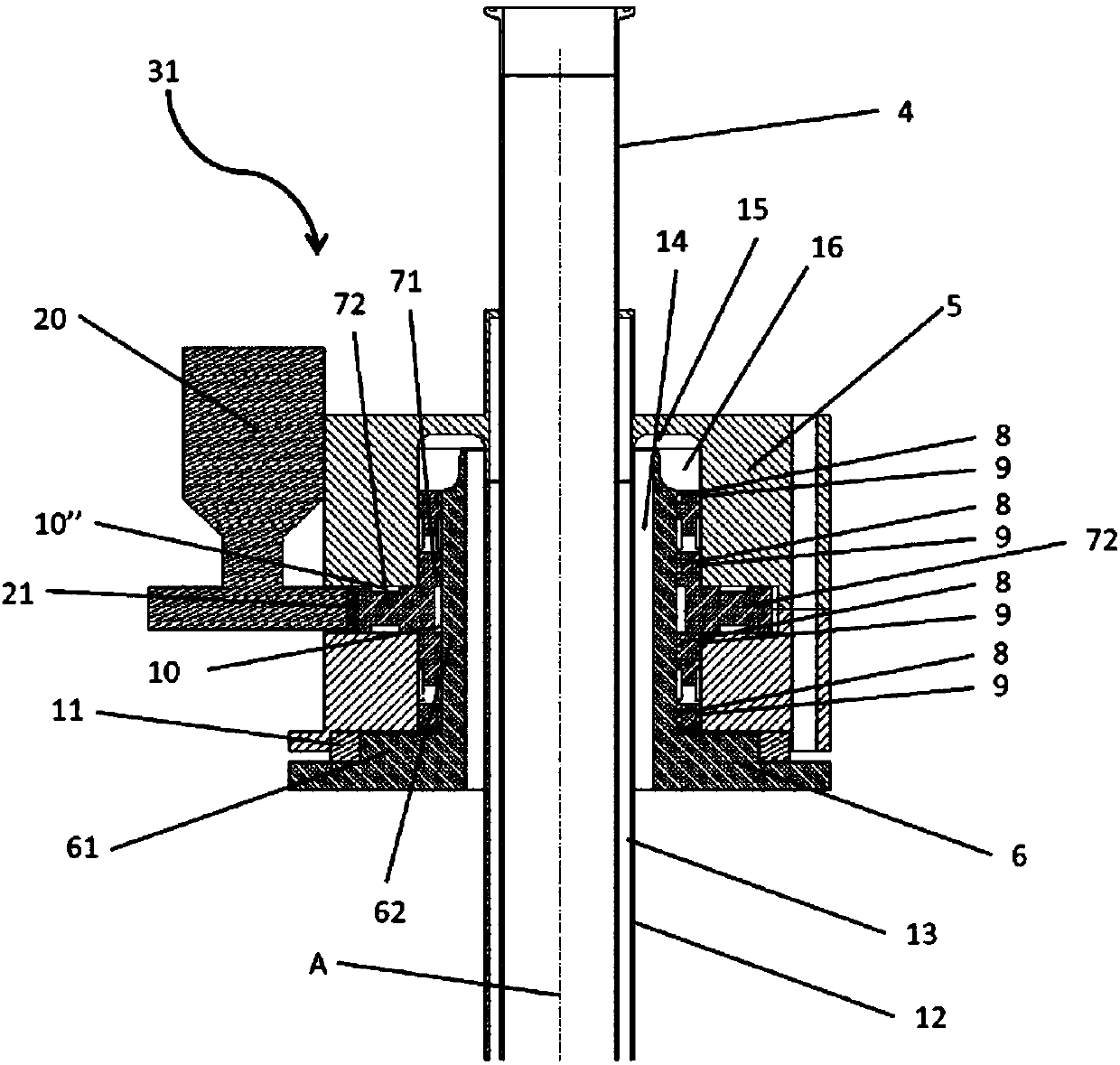
[0027] In this detailed description, embodiments of rotary transfer fillers and rotary devices according to the present invention are mainly discussed with reference to schematic cross-sectional views showing rotary devices according to various embodiments of the invention. It should be noted that this is not meant to limit the scope of the invention, which also applies to other situations, such as other types or variants of rotary transfer fillers compared to the embodiment shown in the drawings or device. Furthermore, the mention of particular components in connection with one embodiment of the invention does not imply that those components cannot be used with other embodiments of the invention. The invention will now be described with reference to the drawings, wherein attention will be given first to structure and second to function.

[0028] figure 1 A schematic cross-sectional view of a carousel filler 1 according to an embodiment of the invention is shown. The rotary...


PUM


Abstract

The invention relates to a swivel arrangement for a carousel filler having a rotating tank (2) and a product pipe (4) for transporting product into the rotating tank. The swivel arrangement comprisesa tank connecting part (6) arranged to rotate with the rotating tank, a product pipe connecting part (5) arranged to at least partly surround the tank connecting part and an intermediate part (7) arranged between the tank connecting part and the product pipe connecting part, the intermediate part is arranged to rotate with a rotational speed different from a rotational speed of the tank connectingpart. The invention also relates to the carousel filler comprising such swivel arrangement.

Description

Background technique [0001] The invention relates to a rotary device for a carousel filler, and the invention also relates to a carousel filler having such a rotary device. Background technique [0002] In the food processing industry, rotary transfer fillers are used to fill packages for different types of beverages. In order to ensure an even distribution of certain types of beverages, eg beverages containing particles or media that may settle, or to ensure a uniform quality, the rotary conveyor filler may have a rotating tank. The rotary tank is refilled into the tank by a product tube extending from above the tank by means of a rotating device. In order to keep the environment in the tank sterile, the rotating device can withstand or accommodate the passage of hot steam and / or sterile air. Therefore, many functions are included and many considerations are made when designing the rotary, since the tank or product requires a sterile environment, which itself consumes a l...

Claims


Application Information

Patent Timeline
Patent Type & Authority Applications(China)
IPC IPC(8): B65B3/00B67C3/22
Inventor 拉斯·安德森
Owner TETRA LAVAL HLDG & FINANCE SA
Learn More