Protector and Harness

A technology for protectors and wires, applied in the direction of circuits or fluid pipelines, insulated conductors, cables, etc., can solve the problems that the cover cannot be stretched and the shape of the protector cannot be changed

Active Publication Date: 2020-11-06
AUTONETWORKS TECH LTD +2
View PDF1 Cites 0 Cited by
  • Summary
  • Abstract
  • Description
  • Claims
  • Application Information

AI Technical Summary

Problems solved by technology

In Patent Document 1, although the main body of the protector is allowed to expand and contract, the cover cannot be stretched, so there is a problem that the cover must be changed to a different shape, otherwise the shape of the protector cannot be changed.

Method used


Image

  • Protector and Harness
  • Protector and Harness
  • Protector and Harness

Examples


Embodiment approach 1

[0038] refer to Figure 1 to Figure 10 Embodiment 1 will be described.

[0039] The wire harness 20 of this embodiment can be used for wiring of vehicles, such as an electric vehicle and a hybrid vehicle, for example, In this embodiment, the power storage module 10 as a drive source for a vehicle is arrange|positioned. In the following description, the X direction is defined as the front, the Y direction is defined as the left side, and the Z direction is defined as the upward direction.

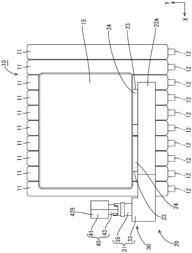
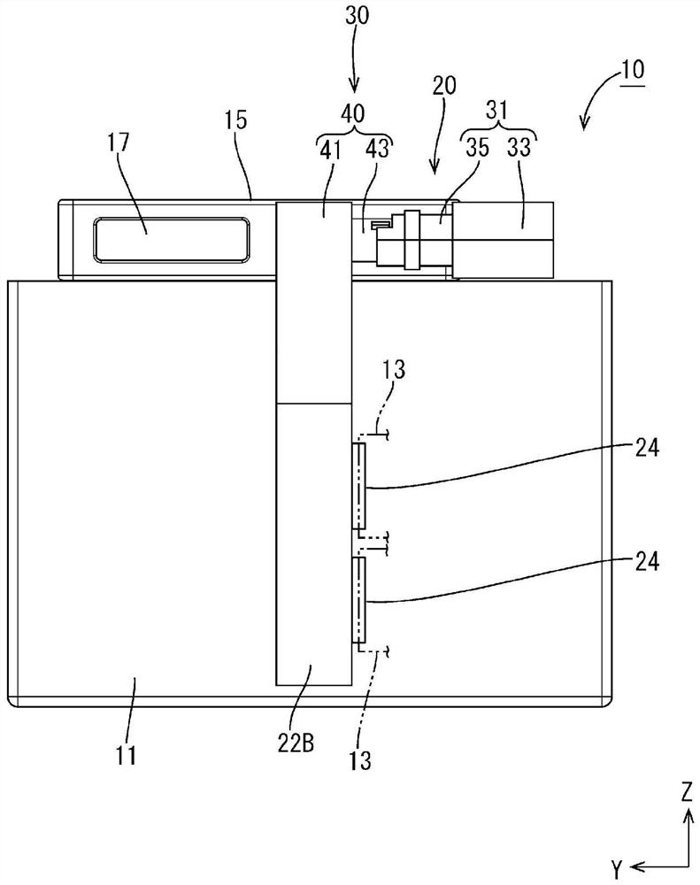
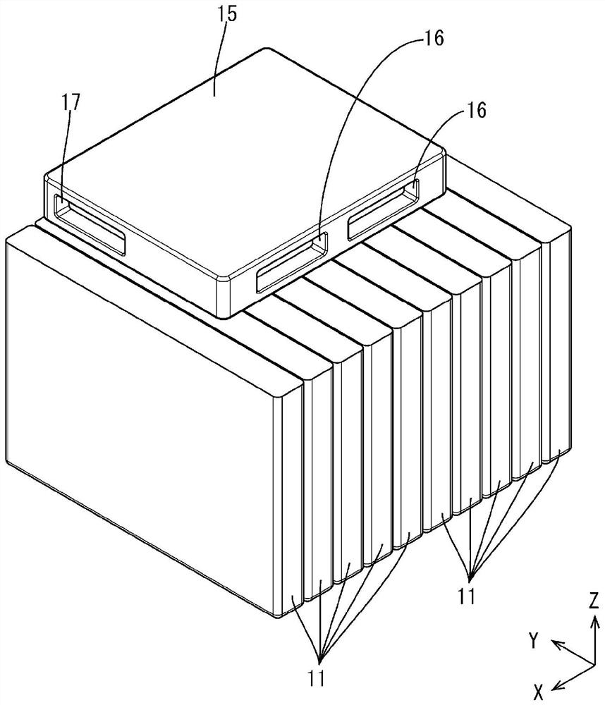
[0040] (Power storage module 10)

[0041] Such as figure 1 As shown, the power storage module 10 includes a plurality (ten in the present embodiment) of power storage elements 11 and an ECU (Electronic Control Unit: electronic control unit) 15 . The plurality of storage elements 11 are formed in a flat substantially cuboid shape, and accommodate storage elements (not shown) therein. A pair of electrode terminals 12 (refer to figure 1 ). Although a pair of electrode terminals 12 are p...

Embodiment approach 2

[0066] For Embodiment 2, refer to Figure 11 ~ Figure 13 Be explained. Embodiment 1 is in the state where the first unit 31 and the second unit 40 are arranged in parallel, and the first unit 31 and the second unit 40 extend in opposite directions; When the two units 52 are arranged in parallel, the first unit 51 and the second unit 52 extend side by side on the same side. Hereinafter, the same reference numerals will be assigned to the same configurations as those in the first embodiment and will be described.

[0067] In addition, a plate-shaped restricting portion 54 protrudes outward from the outer peripheral surface of the second cylindrical portion 53 . The restricting portion 54 moves in the circumferential direction within the range formed by the notch portion 38 . The first unit 51 has a first body part 33 for the insertion of the electric wire 21, and the first body part 33 is connected to the connected part 55. The second unit 52 has a second body part 41 for the...


PUM


Abstract

A protector includes: a first unit into which an electrical wire is to be inserted; and a second unit into which a portion of the electrical wire is to be inserted, the portion being other than a portion that is not to be inserted into the first unit. The first unit includes a coupling-target portion, and the second unit includes a coupling portion that is coupled to the coupling-target portion so as to be rotatable relative to the coupling-target portion.

Description

technical field [0001] This specification discloses a technology related to protectors. Background technique [0002] Conventionally, there is known a technique of covering and protecting electric wires with a protector. The protector of Patent Document 1 is provided with a protector main body and a cover body covering the protector main body. A cover that is shaped according to the bend of the protector body is attached. [0003] prior art literature [0004] patent documents [0005] Patent Document 1: Japanese Patent Laid-Open No. 2014-204582 Contents of the invention [0006] The problem to be solved by the invention [0007] However, it may be desirable to change the shape of the protector in order to improve workability and the like. For example, in order to fit a connector connected to a wire harness covered by a protector, or to avoid a wire harness when tightening a screw under a wire harness covered by a protector, it is sometimes desirable to change t...

Claims


Application Information

Patent Timeline
Patent Type & Authority Patents(China)
IPC IPC(8): H02G3/04B60R16/02H01B7/00
CPCB60R16/0215H02G3/0487H02G3/0608H02G3/04
Inventor 冈本怜也平井宏树田中徹儿平光宏臣清水宏竹田仁司
Owner AUTONETWORKS TECH LTD
Why Eureka
Try Eureka