Automatic screw assembling device and method

An automatic assembly device and screw technology, which is applied in metal processing, metal processing equipment, manufacturing tools, etc., can solve the problems of poor applicability and inability to install multiple screws at the same time, so as to save total time, save material distribution time, and save assembly The effect of time

Pending Publication Date: 2018-03-30
ZHEJIANG TENGEN ELECTRIC
View PDF1 Cites 3 Cited by
  • Summary
  • Abstract
  • Description
  • Claims
  • Application Information

AI Technical Summary

Problems solved by technology

[0005] Therefore, the technical problem to be solved by the present invention is to overcome the problem that the screw

Method used


Image

  • Automatic screw assembling device and method
  • Automatic screw assembling device and method
  • Automatic screw assembling device and method

Examples


Embodiment 1

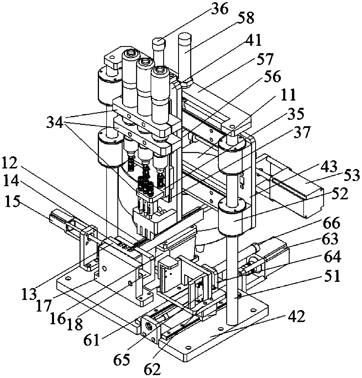
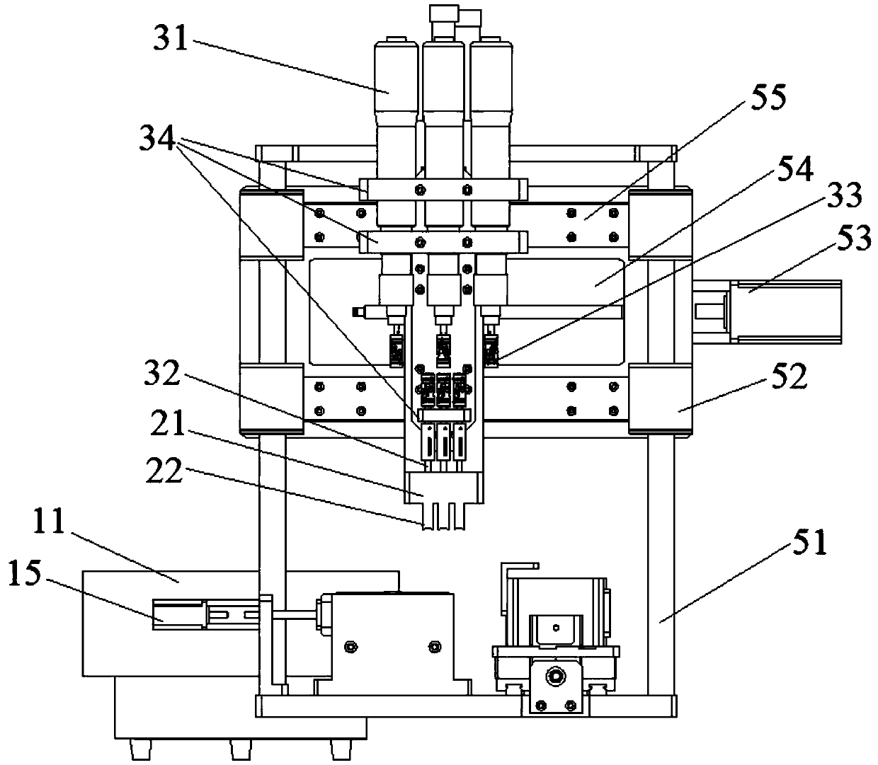
[0068] This embodiment provides an automatic screw assembly device, which includes: a material distribution mechanism, an assembly mechanism, a moving mechanism, and a workpiece positioning fixture.

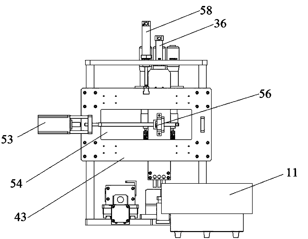
[0069] Among them, the material distribution mechanism is used to output screws regularly. Such as figure 1 as well as Figure 4 As shown, the material distribution mechanism in this embodiment includes a vibration plate 11 , a linear vibrator 12 and a material distribution module 13 . The material distribution module 13 is vertically arranged with the linear vibrator 12, the linear vibrator 12 is connected with the discharge end of the vibration plate 11, and the material distribution module 13 is connected with the discharge end of the linear vibrator 12. The distributing module 13 is provided with three distributing ports for accommodating screws. The material distribution port in this embodiment is a first open groove 14 with one end open, and its opening faces the linear ...

Embodiment 2

[0079] A method for screw assembly using the above-mentioned automatic screw assembly device, comprising the following steps:

[0080] S1: First, carry out the material distribution operation, that is, output the scattered screws from the discharge end of the material distribution mechanism in an orderly manner through the material distribution mechanism; the scattered screws are regularly output to the linear vibrator 12 through the vibrating plate 11; The vibrator 12 is sequentially assigned to the distribution port in the distribution module 13 . Wherein the material distribution module of the present invention moves a material distribution port to the discharge port end of the linear vibrator 12 at a time under the drive of the stepping motor 15, and the material distribution module is provided with 3 material distribution ports, the distribution port of the present invention The material module 13 performs a distributing operation during the reciprocating movement, so the...


PUM


Abstract

The invention discloses a screw automatic assembly device, which comprises: a material distribution mechanism, which regularly outputs screws; an assembly mechanism, the assembly mechanism includes at least one execution unit, and the execution unit assembles the screw to a workpiece; The assembly mechanism also includes a retrieving unit connected to the execution unit, the retrieving unit is set correspondingly to the discharge end of the distributing mechanism; the screw automatic assembly device also includes a moving mechanism, the moving mechanism is connected with the assembling mechanism, and the moving mechanism drives the assembling mechanism to move between the picking position and the assembling position. In the screw automatic assembly device of this structure, the feeding unit and the distributing mechanism are set correspondingly, and multiple screws can be taken out at the same time, and driven into the assembly position through multiple execution units; due to the setting of the feeding unit, it can be moved under the drive of the moving mechanism. Solved the problem that the dispensing mechanism is not at the same position as the assembly position.

Description

technical field [0001] The invention relates to the technical field of assembly equipment, in particular to an automatic screw assembly device and an assembly method. Background technique [0002] In many manufacturing fields, a large number of screws are used, and screws are usually assembled by manual assembly. The way of manually assembling screws is not only time-consuming, but also has low assembly efficiency, high labor intensity, unstable assembly quality, and cannot meet the needs of the development of automated production. [0003] In order to solve the above-mentioned technical problems, Chinese patent document CN202240416U discloses a terminal screw automatic assembly machine, the terminal and the screw are respectively sent to the terminal positioning index plate and the screw index plate through the arrangement of the vibrating plate and the linear vibrator, and the terminal The edge of the positioning index plate is provided with a plurality of grooves around ...

Claims


Application Information

Patent Timeline
IPC IPC(8): B23P19/06
CPCB23P19/001B23P19/06
Inventor 方艳东
Owner ZHEJIANG TENGEN ELECTRIC
Why Eureka
Try Eureka