

a dispenser
A liquid dispenser and liquid separation technology, which is applied in the direction of measuring tube/suction pipe, etc., can solve the problems of cumbersome operation and high operator requirements, and achieve the effect of simplifying the operation process, saving liquid dispensing time, and reducing requirements
- Summary
- Abstract
- Description
- Claims
- Application Information
AI Technical Summary
Problems solved by technology
Method used
Image

Examples
Embodiment 1
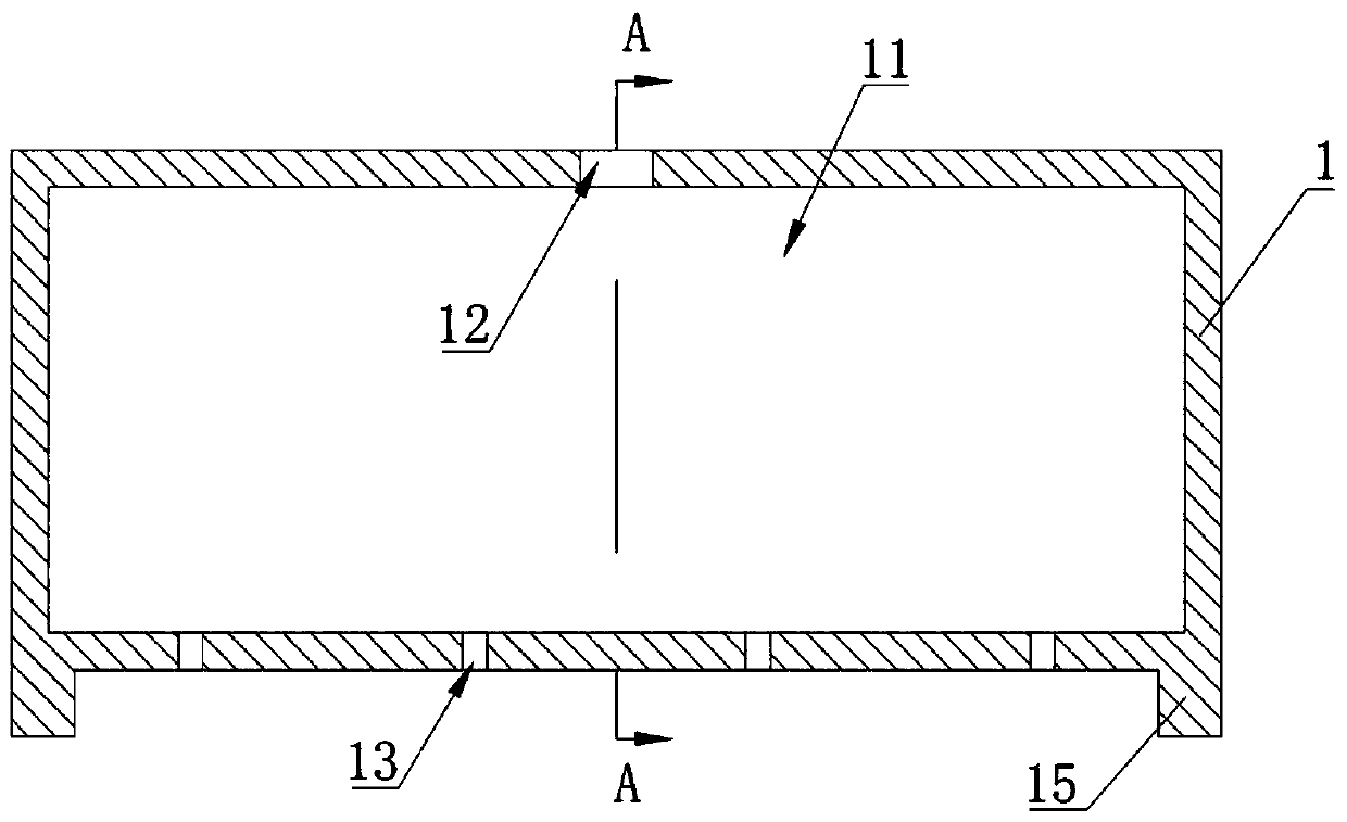
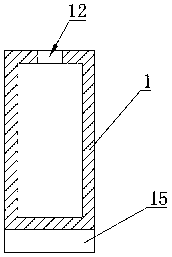
[0026] Such as figure 1 and figure 2 As shown, this embodiment provides a liquid dispenser for distributing the same liquid into multiple containers through the liquid dispenser. The liquid dispenser includes a liquid dispenser housing 1 provided with a cavity 11, and the liquid dispenser housing 1 is provided with a liquid inlet 12 and a plurality of liquid outlets 13; the liquid inlet 12 and the liquid outlet 13 Both are in communication with the cavity 11; the housing 1 of the liquid dispenser is also provided with a positioning piece 15, which is used for the positioning of the liquid dispenser and the porous plate to be liquid-separated.
[0027] By providing multiple liquid outlet holes 13, liquid can be added to multiple holes on the perforated plate at the same time. The liquid separator has a simple structure, is easy to process, has low production cost, and improves liquid separation efficiency. In this embodiment, the liquid outlet holes 13 are distributed in fou...
Embodiment 2
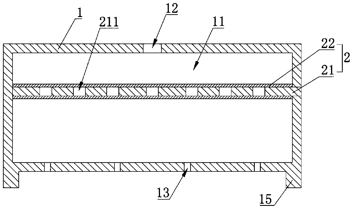
[0037] Such as image 3 As shown, in this embodiment, on the basis of the first embodiment, a filter device 2 is added in the cavity 11 for filtering the liquid that will flow out through the liquid outlet hole 13 .
[0038] Specifically, the liquid inlet hole 12 and the liquid outlet hole 13 are respectively located on both sides of the filter device 2; the cavity 11 is divided into upper and lower chambers by the filter device 2, so that the liquid enters the upper chamber through the liquid inlet hole 12. In the chamber, the liquid enters the lower chamber after being filtered by the filter device 2 , and then flows out through a plurality of liquid outlet holes 13 . Using the filter device 2 to filter the liquid can prevent the liquid entering the holes on the perforated plate from being polluted when the liquid flowing out through the liquid outlet hole 13 contains impurities.
[0039] The filter device 2 includes a filter plate 21 detachably connected to the liquid sepa...
Embodiment 3
[0044] Such as Figure 4 As shown, the difference between this embodiment and Embodiment 1 is that in this embodiment, a liquid outlet pipe 14 extends downward from the bottom of the liquid outlet hole 13 , and the inner diameter of the liquid outlet pipe 14 is the same as that of the liquid outlet hole 13 . By setting the liquid outlet pipe 14, it is convenient to make the liquid outlet pipe 14 correspond to the corresponding holes on the perforated plate one by one, ensuring that the liquid flowing out from the liquid outlet hole 13 will not flow to the hole on the perforated plate corresponding to the adjacent liquid outlet hole 13 Inner or perforated plate.
[0045] The liquid outlet pipe 14 is integrally formed with the liquid distributor housing 1, which can simplify the structure of the liquid distributor, simplify the processing technology and reduce the production cost. The liquid outlet pipe 14 and the liquid separator housing 1 are integrally molded by mold integra...
PUM
 Abstract
Description
Claims
Application Information