
Electric injecting device of injection molding machine

A technology of injection device and injection molding machine, which is applied in the field of injection device, can solve the problems of precision improvement, troublesome installation and maintenance, etc., and achieve the effects of improved plasticizing precision, convenient installation and maintenance, and high transmission ratio

Pending Publication Date: 2018-03-30
周飞
View PDF0 Cites 1 Cited by
  • Summary
  • Abstract
  • Description
  • Claims
  • Application Information

AI Technical Summary

Problems solved by technology

The specific composition and coordination relationship of the barrel assembly, pre-molding mechanism and injection mechanism are various, but there are deficiencies in precision that need to be improved and installation and maintenance troublesome.

Method used


Image

  • Electric injecting device of injection molding machine
  • Electric injecting device of injection molding machine
  • Electric injecting device of injection molding machine

Examples


Embodiment 1

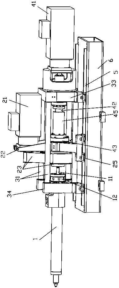
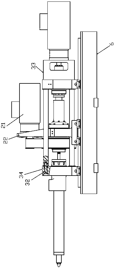
[0021] Such as figure 1 , 2 As shown, the electric injection device of the injection molding machine includes a barrel assembly 1, an injection base assembly, a pre-plasticizing mechanism, and an injection mechanism.

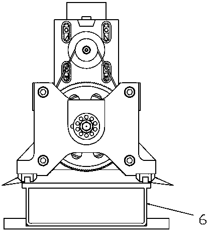
[0022] Such as image 3 , 4 As shown, the above-mentioned shooting base assembly includes a shooting front plate 34, a shooting back plate 33, a shooting rod 31 and a bolt 32. The shooting front plate 34 and the shooting back plate 33 are connected by the shooting rod 31 and the nut 32 respectively. Together, the two bottoms of the front plate 34 of the shooting table are respectively provided with front slides of the shooting table, each of the front slides of the shooting table is placed on the linear guide 5 respectively, and the bottom of the two sides of the shooting table rear plate is also provided with the shooting table rear plate. The sliders, each of the rear plate sliders of the shooting platform are respectively placed on the linear guide 5.

[0023] The...

Embodiment 2

[0030] The injection motor 41 in the first embodiment is fixed on the inner side of the pre-plastic seat 22.

[0031] The transmission mechanism of this embodiment includes synchronous wheels 48, 49, a synchronous belt 47 and an injection screw nut. One synchronous wheel 49 is fixed on the motor shaft of the injection motor 41, the other synchronous wheel 48 is fixed on the injection screw, and two The synchronous wheels 48 and 49 are connected by a synchronous belt 47.

[0032] The rest of the structure is the same as in Example 1.


PUM


Abstract

An electric injecting device of an injection molding machine comprises an injection table seat assembly, a pre-plasticizing mechanism, linear guiding rails, a base and an injection mechanism. The injection table seat assembly comprises an injection table front plate, an injection table rear plate and injection table pull rods. The four corners of the injection table front plate and the four corners of the injection table rear plate are connected through the injection table pull rods correspondingly, and the bottoms of the injection table front plate and the injection table rear plate are supported and guided through the linear guiding rails correspondingly. The pre-plasticizing mechanism comprises a plasticizing power device and a pre-plasticizing seat, the plasticizing power device is fixed to the pre-plasticizing seat and drives a screw to rotate, the bottom of the pre-plasticizing seat is supported and guided through the linear guiding rails, and the linear guiding rails are arranged on the base. The injection mechanism comprises an injection power device and a transmission mechanism, and the injection power device is fixed to the injection table rear plate and moves the pre-plasticizing seat through the transmission mechanism.

Description

Technical field [0001] The invention relates to an injection device of an injection molding machine. Background technique [0002] The electric injection device of the existing injection molding machine generally includes a barrel assembly, a pre-molding mechanism and an injection mechanism; the pre-molding mechanism includes a pre-molding motor, a transmission mechanism and a pre-molding seat; the pre-molding motor and the transmission mechanism are fixed on the pre-molding seat, The plastic motor drives the screw in the injection barrel through the transmission mechanism to pre-plastic the raw materials in the barrel; the injection mechanism includes an injection motor and a screw nut transmission mechanism. The injection motor drives the preplastic seat through the screw nut transmission mechanism to make The pre-plastic seat pushes the screw forward for injection molding, the barrel assembly is fixed on the front plate of the injection table, and the injection motor is fixed ...

Claims


Application Information

Patent Timeline
IPC IPC(8): B29C45/47B29C45/17
CPCB29C45/17B29C45/1747B29C45/47B29C2045/1792
Inventor 周飞
Owner 周飞
Learn More