
Apparatus used for arranging and realizing circuit right angle switching in electric power rail

A power rail, right-angle technology, which is applied to the parts, circuits, coupling devices and other directions of the connection device, can solve the problems that the power rail cannot be tightly connected, the splicing is not easy to achieve the desired effect, and the splicing gap is easy to move flexibly and solve the problems. Difficult installation, enhanced security effect

Inactive Publication Date: 2018-03-30
SHANUTEC (SHANGHAI) CO LTD
View PDF5 Cites 0 Cited by
  • Summary
  • Abstract
  • Description
  • Claims
  • Application Information

AI Technical Summary

Problems solved by technology

[0002] The existing device (technology) can realize the right-angle transfer of the circuit at the positive and negative corners of the wall, but due to the deviation between the measured size of the wall and the actual size, there are different degrees of error between the length of the power track cut according to the measured size and the actual installation size. As a result, the connection between the power track and the male and female corners cannot be tightly connected, there is a gap, and the conductor is exposed; in addition, the cover plate of the existing device is made of two pieces of stainless steel, which is complicated to install, and the splicing is not easy to achieve the desired effect, leaving a splicing gap

Method used


Image

  • Apparatus used for arranging and realizing circuit right angle switching in electric power rail
  • Apparatus used for arranging and realizing circuit right angle switching in electric power rail
  • Apparatus used for arranging and realizing circuit right angle switching in electric power rail

Examples


Embodiment 1

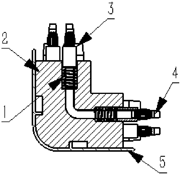
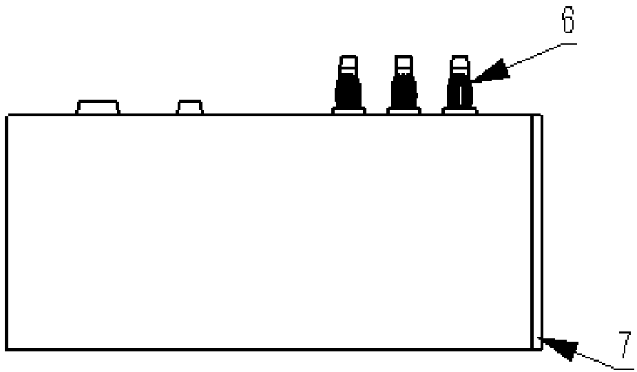
[0028] Such as figure 1 with figure 2 As shown, this embodiment provides a device for the layout of power rails to realize the right-angle transfer of circuits, which is installed at the male and female corners of the wall, and is used to realize the right-angle transfer of power rails, including the transfer main part, insulation protection tube, conductive rod and lantern head, the conductive rod is fixed inside the transfer main part, the insulating protection tube and lantern head are sleeved on the conductive rod in turn, the device also includes a spring, the spring is sleeved on the conductive rod and connected with the insulating protection tube. The device for power track arrangement to realize circuit right-angle transfer also includes a housing, which is installed outside the transfer main part. The casing includes a shell and an upper cover. The shell is installed on the side surface of the transfer main part not in contact with the wall, and the upper cover is i...

Embodiment 2

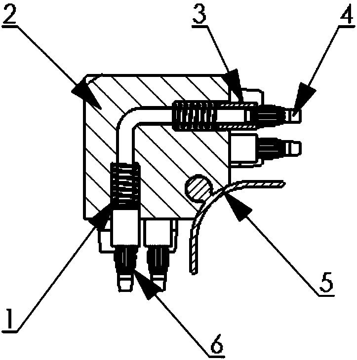
[0031] Such as image 3 with Figure 4 As shown, the device in this embodiment is substantially the same as the device in Embodiment 1, except that the device used in this embodiment for power track layout to realize circuit right-angle transfer is installed at the inner corner of the wall, that is, the concave corner, Therefore from image 3 It can be seen from the figure that the outer shell of the device in this embodiment is installed on the inner surface of the main adapter, the inner surface is arc-shaped, the outer surface of the main adapter is at right angles, and the upper cover is installed on the upper surface of the main adapter. When the device is in use, it is close to the inner recess of the wall corner, the copper rods on both sides are aligned with the copper pipes of the power track, and inserted into two right-angled tracks to use.


PUM


Abstract

The invention relates to an apparatus used for arranging and realizing circuit right angle switching in an electric power rail. The apparatus is installed at inside and outside corners of a wall surface and is used for realizing right angle switching of the electric power rail. The apparatus comprises a switching main component, an insulation protection tube, a conducting rod and a lantern head. The conducting rod is fixedly arranged in the switching main component. The insulation protection tube and the lantern head successively sleeve the conducting rod. The apparatus also comprises a spring. The spring sleeves the conducting rod and is connected to the insulation protection tube. Compared with the prior art, by using the apparatus of the invention, there are advantages that installationis tight; a conductor is not exposed; safety performance is high; and installation is convenient and so on.

Description

technical field [0001] The invention relates to a switching device, in particular to a device for power track arrangement to realize circuit right-angle switching. Background technique [0002] The existing device (technology) can realize the right-angle transfer of the circuit at the positive and negative corners of the wall, but due to the deviation between the measured size of the wall and the actual size, there are different degrees of error between the length of the power track cut according to the measured size and the actual installation size. As a result, the connection between the power track and the male and female corners cannot be tightly connected, there is a gap, and the conductor is exposed; in addition, the cover plate of the existing device is made of two pieces of stainless steel, which is complicated to install, and the splicing is not easy to achieve the desired effect, leaving a splicing gap. Contents of the invention [0003] The object of the present...

Claims


Application Information

Patent Timeline
Patent Type & Authority Applications(China)
IPC IPC(8): H01R4/72H01R13/502H01R31/06
CPCH01R4/72H01R13/502H01R31/06
Inventor 朱文廷
Owner SHANUTEC (SHANGHAI) CO LTD
Learn More