Pulse diagnosis probe for diagnosing diseases based on intelligent terminal

An intelligent terminal and pulse diagnosis technology, applied in the electronic field, can solve the problems of poor control, incomplete signal, affecting the accuracy of pulse diagnosis, etc., and achieve the effect of improving the ability, improving the integrity, and improving the accuracy of pulse diagnosis.

Inactive Publication Date: 2018-04-03
SHANGHAI JIAOXUN INTELLIGENT TECH CO LTD
View PDF0 Cites 0 Cited by
  • Summary
  • Abstract
  • Description
  • Claims
  • Application Information

AI Technical Summary

Problems solved by technology

The pressure of the second electronic probe on the wrist skin is often poorly controlled, which may easily cause the detected pulse signal to be incomplete
The signal is incomplete, which can easily affect the accuracy of pulse diagnosis

Method used


Image

  • Pulse diagnosis probe for diagnosing diseases based on intelligent terminal
  • Pulse diagnosis probe for diagnosing diseases based on intelligent terminal
  • Pulse diagnosis probe for diagnosing diseases based on intelligent terminal

Examples


Embodiment Construction

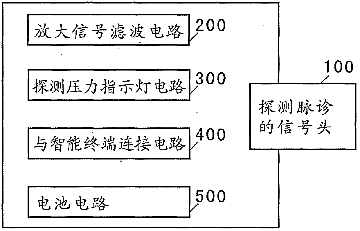
[0021] see figure 1 , the pulse detection signal head 100 applies slight pressure to the patient's wrist skin to collect pulse diagnosis signals. The pulse diagnosis signal is sent to the amplified signal filter circuit 200 to amplify the signal and filter out the interfering signal. Then connect with the smart terminal by connecting the circuit 400 with the smart terminal. In addition, there is a detection pressure indicator circuit 300, which can indicate the correct pressure of the pulse diagnosis. There is also a battery circuit 500 for power.

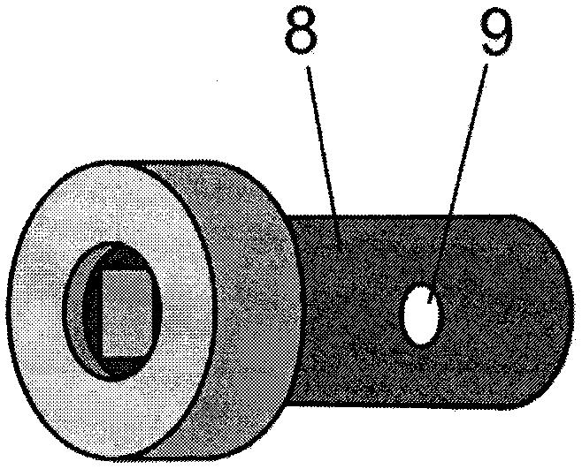
[0022] see figure 2 , pulse diagnosis probe, the present embodiment adopts the working mode of the electromagnetic seismic probe.

[0023] State the force of the spring. One end of the spring 3 is pressed on the spring pressing plate 18, and the other end is pressed on the top of the T-shaped thimble 4. The T-shaped thimble 4 is pushed against the electromagnet core 15 at the other end. The electromagnet core 15 is connecte...


PUM


Abstract

A pulse diagnosis probe based on an intelligent terminal for diagnosis; including: a signal head for pulse detection, an amplified signal filter circuit, a pressure detection indicator circuit, a connection circuit with an intelligent terminal, and a battery circuit. For detection, use a resistance strain gauge, or a pickup, or a piezoelectric ceramic sheet, or an electromagnetic shock probe; and a spring applies a signal head for pulse detection, which exerts slight pressure on the skin of the wrist. The amplified signal filtering circuit refers to amplifying and filtering the electronic signal of the detection pulse diagnosis signal head. The innovative invention of the pulse diagnosis probe for diagnosis can clearly collect the pulse diagnosis signal with the help of the fixed sleeve. When the pressure on the wrist is normal, there is an indicator light to prompt. It is beneficial to control the pressure of electronic pulse diagnosis in the normal range. Significantly improve the signal integrity of pulse diagnosis and improve the accuracy of pulse diagnosis. The pulse diagnosis probe of the present invention is suitable for ordinary users to use in homes, offices and hospital outpatient rooms.

Description

technical field [0001] The invention relates to electronic technology, in particular to a pulse diagnosis probe based on an intelligent terminal for diagnosis. Background technique [0002] Traditional Chinese medicine can diagnose many diseases of the human body through the doctor's finger, pulse diagnosis (also known as: Tiemai) on the patient's wrist, together with interrogation and inspection. Very miraculous. [0003] There is a wide range of market demands for pulse diagnosis based on smart terminals. However, electronic pulse diagnosis often has two major obstacles. The first probe pulse signal is incomplete. The pulse signal has not only the beating frequency, but also the pulse beating curve and other characteristics. The pressure of the second electronic probe on the skin of the wrist is often poorly controlled, which may easily cause the detected pulse signal to be incomplete. Incomplete signals can easily affect the accuracy of pulse diagnosis. Contents of...

Claims


Application Information

Patent Timeline
IPC IPC(8): A61B5/02A61B5/00
CPCA61B5/02A61B5/0002A61B5/4854A61B5/7203A61B5/7225
Inventor 许春茂许晋
Owner SHANGHAI JIAOXUN INTELLIGENT TECH CO LTD
Why Eureka
Try Eureka