Jet nozzle, water jet scalpel apparatus, jet nozzle molding method and water jet scalpel apparatus molding method
A technology of nozzles and instruments, applied in the direction of fluid jet scalpels, syringes, medical science, etc., to achieve the effect of reducing loss and reducing liquid loss
- Summary
- Abstract
- Description
- Claims
- Application Information
AI Technical Summary
Problems solved by technology
Method used
Image

Examples
Embodiment 1
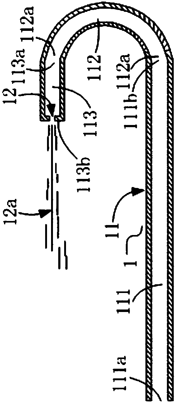
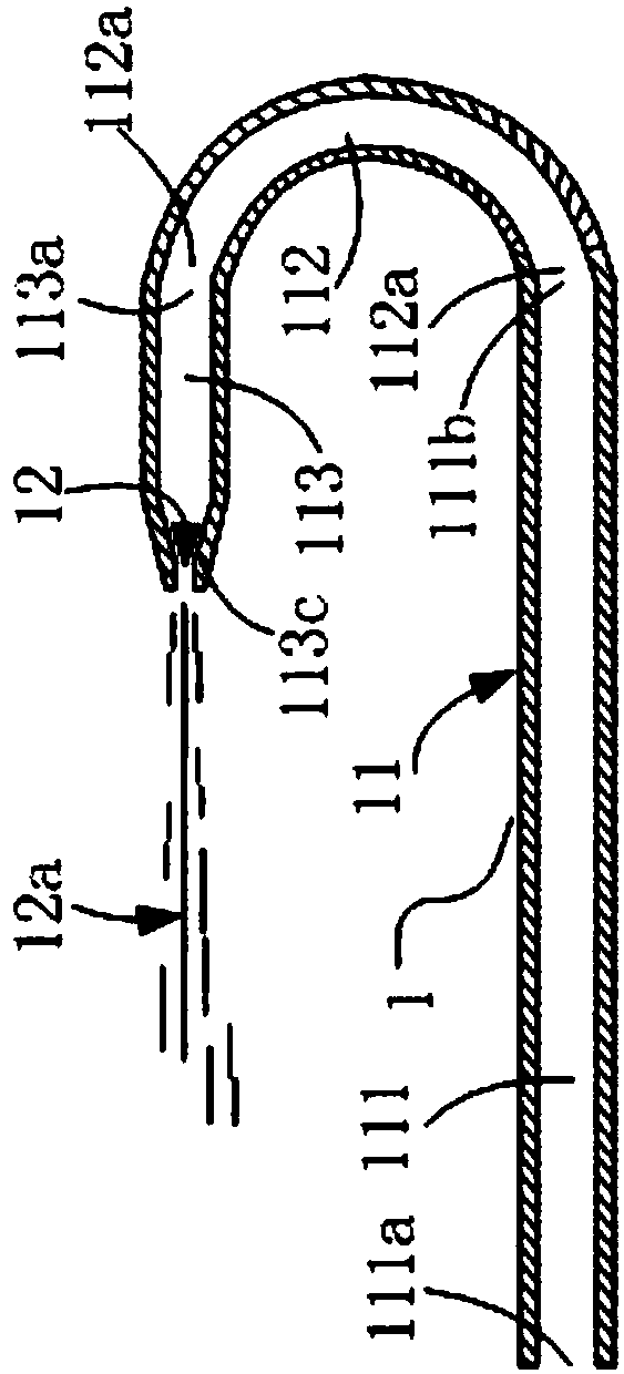
[0085] image 3 and 4 Two structural implementations of the nozzle 1 are shown. In this example, the elbow portion 112 is a 180-degree elbow, and the nozzle hole 12 is formed on the convex head 113c. The difference between the two structural implementations is mainly in the convex head 113c shape.
[0086] Please refer to image 3 and 4 The structure of the nozzle 1 provided in this embodiment includes: a liquid inlet pipe 11 and a nozzle hole 12, the liquid inlet pipe 11 is used to provide a flow path for the high-pressure liquid to flow to the nozzle hole 12, and the near end of the liquid inlet pipe 11 is provided with a nozzle hole 12 , the remote end is connected to a high-pressure liquid supply source, and the high-pressure liquid flows from the liquid inlet pipe 11 to the nozzle hole 12; the nozzle hole 12 is used to form a liquid jet 12a when the high-pressure liquid flows through. Wherein, the liquid inlet tube 11 includes: a distal straight pipe portion 111, an e...
Embodiment 2
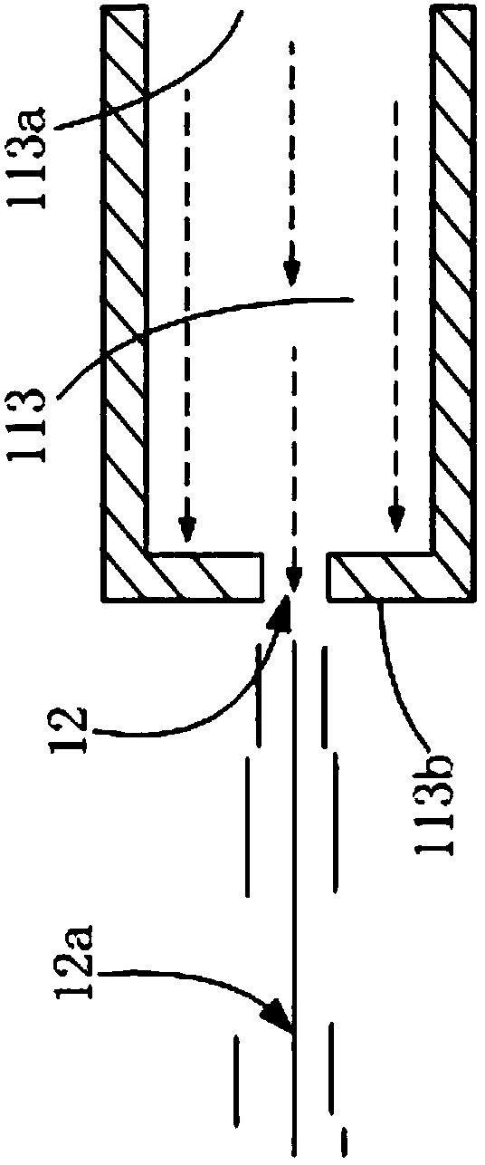
[0103] This example provides a nozzle with another structure and a molding method for the nozzle. The difference between the nozzle structure in this example and the nozzle structure in Embodiment 1 is that when the elbow portion 112 is a 180-degree elbow, the nozzle hole 12 is formed on the pipe wall of the proximal straight pipe portion 113, and is aligned with the convex head 113c forms a gap. Wherein, the nozzle hole 12 can be formed on the inner tube wall or the outer tube wall of the proximal straight tube portion 113 . The nozzle forming method in this example is different from the nozzle forming method in Embodiment 1 in that in S3, the nozzle hole 12 is formed on the tube wall of the proximal straight tube portion 113 and forms a distance from the convex head 113c. Wherein, the nozzle hole 12 can be formed on the inner tube wall or the outer tube wall of the proximal straight tube portion 113 . When the nozzle hole 12 is formed on the tube wall of the proximal strai...
Embodiment 3
[0105] Figure 7 and 8 Two other structural implementations of the nozzle 1 are shown. In this example, the elbow portion 112 is a 90-degree elbow. The difference between the two structural implementations mainly lies in the shape of the convex head 113c.
[0106] Please refer to Figure 7 and 8 The structure of the nozzle 1 provided in this embodiment includes: a liquid inlet pipe 11 and a spray hole 12, and the liquid inlet pipe 11 includes: a distal straight pipe portion 111, an elbow portion 112, and a proximal straight pipe portion 113, and the distal straight pipe Part 111, curved pipe part 112 and proximal straight pipe part 113 all have pipe wall and pipe lumen respectively. The inner cavity of the tube continues to flow toward the nozzle hole 12, and when passing through the nozzle hole 12, various required liquid jets 12a of different shapes are formed and ejected.
[0107] The far-end straight pipe part 111 has a first liquid inlet 111a and a liquid outlet 111b....
PUM
 Abstract
Description
Claims
Application Information
 - R&D
- Intellectual Property
- Life Sciences
- Materials
- Tech Scout
- Unparalleled Data Quality
- Higher Quality Content
- 60% Fewer Hallucinations
Browse by: Latest US Patents, China's latest patents, Technical Efficacy Thesaurus, Application Domain, Technology Topic, Popular Technical Reports.
© 2025 PatSnap. All rights reserved.Legal|Privacy policy|Modern Slavery Act Transparency Statement|Sitemap|About US| Contact US: help@patsnap.com