
Detection system and detection method of mixed current transformer

A technology of current transformer and detection system, which is applied in the direction of instruments, measuring devices, and measuring electrical variables, etc., can solve problems such as incorrect action of protection, reduction of reliability and sensitivity of differential protection action, and influence on normal operation of power transmission system. Achieve the effect of improving reliability and sensitivity

Inactive Publication Date: 2018-04-03
CHINA ELECTRIC POWER RES INST +1
View PDF6 Cites 3 Cited by
  • Summary
  • Abstract
  • Description
  • Claims
  • Application Information

AI Technical Summary

Problems solved by technology

"Eighteen Major Power Grid Anti-Accident Measures of the State Grid Corporation" stipulates that the relevant characteristics of the current transformers on each side of the differential protection of the main equipment should be consistent, so as to avoid the transient characteristics of the current transformers on each side when encountering a large short-circuit current. Inconsistencies lead to incorrect action of protection
However, in the process of substation expansion and transformation, in order to reduce the amount of engineering and reduce costs, the characteristics of the current transformers for differential protection are actually difficult to be completely consistent, and it is often the case that different types of current transformers are operated in parallel.
In line longitudinal protection, busbar differential protection, and transformer differential protection, the mixed use of conventional transformers and electronic transformers will lead to misoperation of differential protection, reduce the reliability and sensitivity of differential protection operations, and affect power transmission. normal operation of the system

Method used


Image

  • Detection system and detection method of mixed current transformer
  • Detection system and detection method of mixed current transformer

Examples


Embodiment Construction

[0038] The specific implementation manner of the technical solution of the present invention will be described in further detail below in conjunction with the accompanying drawings.

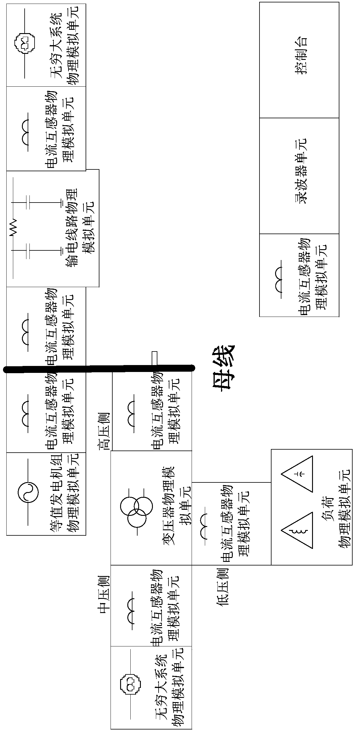
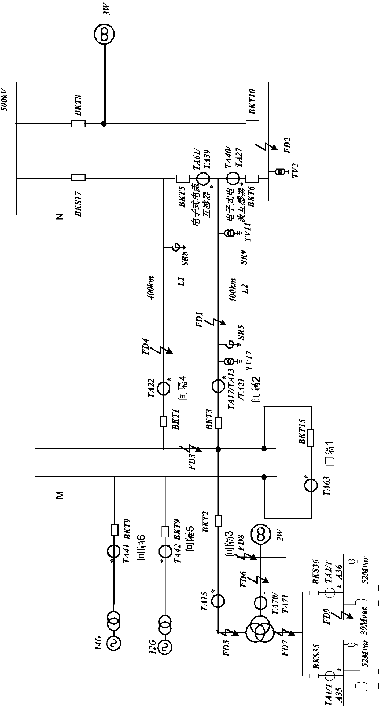
[0039] The technical solution of the present invention is to establish a power system dynamic simulation system containing multiple types of current transformer simulation units, including: equivalent generator set physical simulation unit, load physical simulation unit, infinite system physical simulation unit, transformer physical simulation unit, power transmission Line physical simulation unit, current transformer physical simulation unit group, wave recorder unit and console; according to figure 1 as shown,

[0040] The low-voltage side, medium-voltage side and high-voltage side of the transformer physical simulation unit are respectively connected to the load physical simulation unit through three current transformer physical simulation units in the current transformer physical simulation u...


PUM


Abstract

The invention provides a detection system of a mixed current transformer. A low-voltage side, a medium-voltage side and a high-voltage side of a transformer physical simulation unit of the system arerespectively connected with a load physical simulation unit, an infinite system physical simulation unit and one end of a busbar through three of current transformer physical simulation units constituting a current transformer physical simulation unit group. The other end of the busbar is connected with an equivalent generator set physical simulation unit and a transmission line physical simulation unit respectively through another two current transformer physical simulation units in the current transformer physical simulation unit group. The detection system of the mixed current transformer provided by the invention is equivalent to an actual system, can simulate a mixed operation mode and operation characteristics of the mixed current transformer in the actual system, and can improve thereliability and sensitivity of differential protection actions.

Description

technical field [0001] The invention relates to a detection system and a detection method of a current transformer, in particular to a detection system and a detection method of a hybrid current transformer. Background technique [0002] In order to reduce the impact of current transformer unbalanced current on differential protection and improve the reliability and sensitivity of differential protection action, not only should a single current transformer meet the requirements of the transmission system, but also the current mutual inductance of each side of the transmission system should be considered. The characteristics of the device and the mutual cooperation. "Eighteen Major Power Grid Anti-Accident Measures of the State Grid Corporation" stipulates that the relevant characteristics of the current transformers on each side of the differential protection of the main equipment should be consistent, so as to avoid the transient characteristics of the current transformers ...

Claims


Application Information

Patent Timeline
IPC IPC(8): G01R35/02
CPCG01R35/02
Inventor 廖文彪陈争光詹荣荣李岩军周春霞周泽昕詹智华董明会余越
Owner CHINA ELECTRIC POWER RES INST
Learn More