Supercharge Your Innovation With Domain-Expert AI Agents!

Modular speed reducer and planar multi-joint robot

A technology of plane multi-joint and deceleration device, applied in the field of automation, can solve the problem of outputting a fixed speed and achieve the effect of strong product force

Pending Publication Date: 2018-04-06
SHENZHEN YUEJIANG TECH CO LTD
View PDF0 Cites 0 Cited by
  • Summary
  • Abstract
  • Description
  • Claims
  • Application Information

AI Technical Summary

Problems solved by technology

[0004] The purpose of the present invention is to provide a modular deceleration device and a planar multi-joint robot, aiming at the problem that the planar multi-joint robot in the prior art can only output a fixed speed

Method used

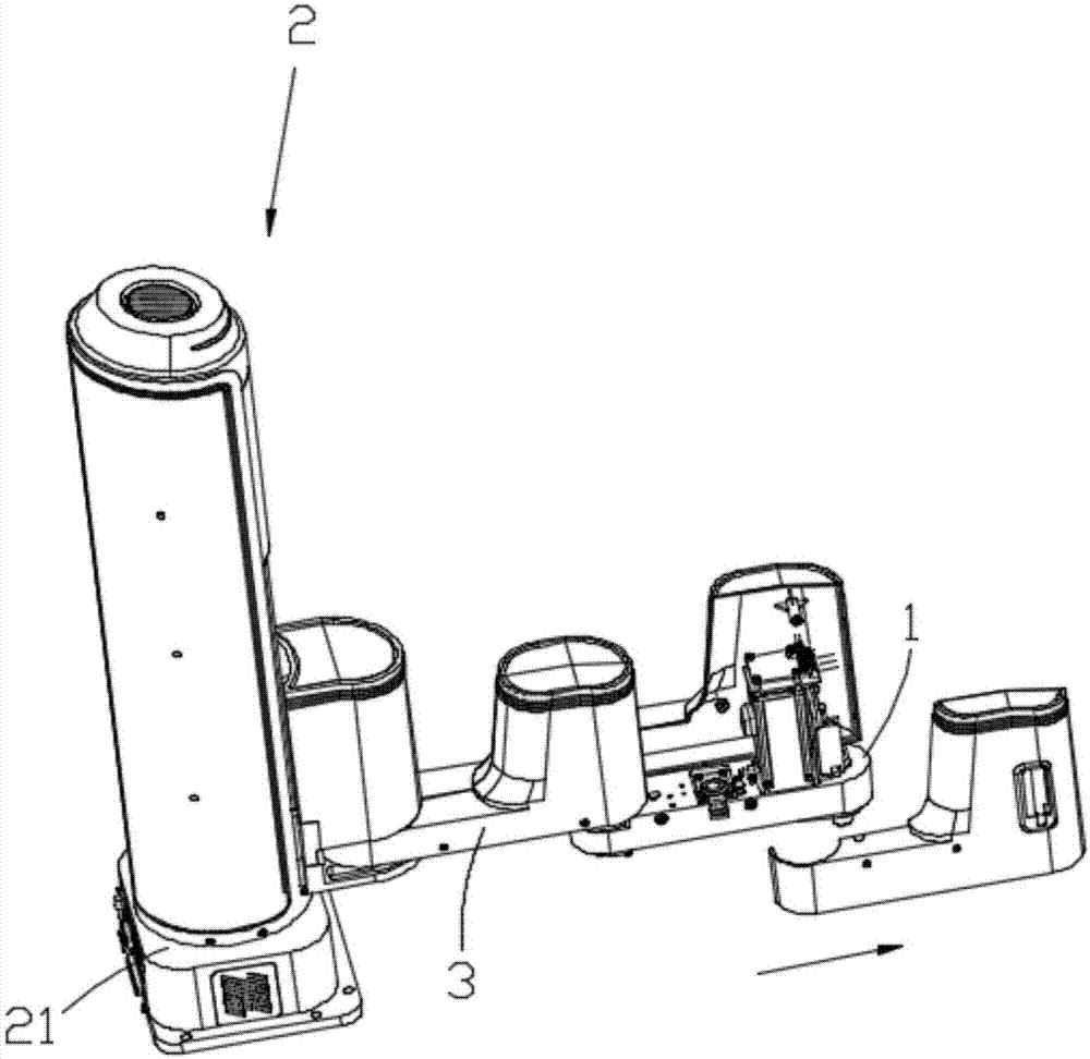
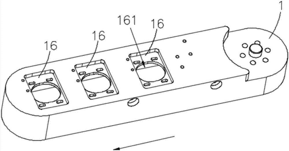
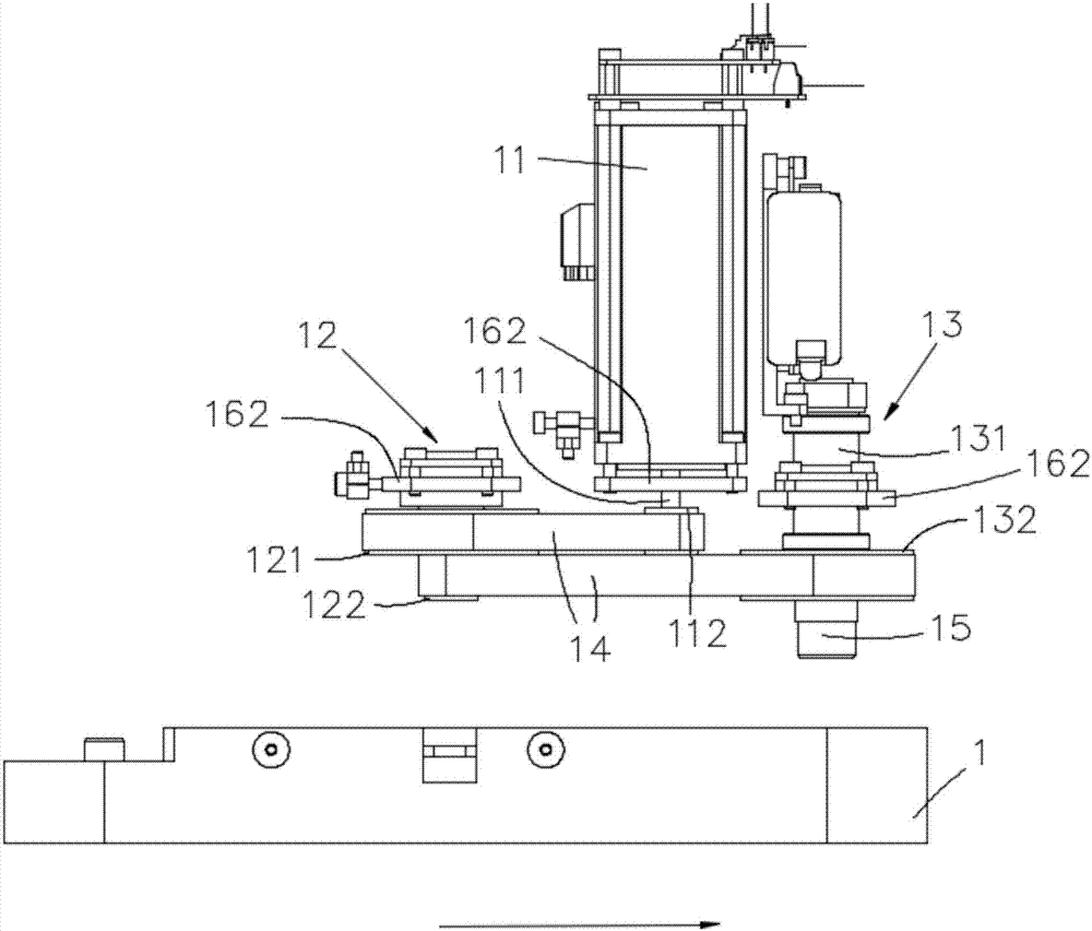

Image

  • Modular speed reducer and planar multi-joint robot
  • Modular speed reducer and planar multi-joint robot
  • Modular speed reducer and planar multi-joint robot

Examples


Embodiment Construction

[0021] In order to make the object, technical solution and advantages of the present invention clearer, the present invention will be further described in detail below in conjunction with the accompanying drawings and embodiments. It should be understood that the specific embodiments described here are only used to explain the present invention, not to limit the present invention.

[0022] In describing the present invention, it should be understood that the terms "length", "width", "upper", "lower", "front", "rear", "left", "right", "vertical", The orientation or positional relationship indicated by "horizontal", "top", "bottom", "inner", "outer", etc. are based on the orientation or positional relationship shown in the drawings, and are only for the convenience of describing the present invention and simplifying the description, rather than Nothing indicating or implying that a referenced device or element must have a particular orientation, be constructed, and operate in a ...


PUM


Abstract

The invention relates to the technical field of automation, and discloses a modular speed reducer and a planar multi-joint robot. The modular speed reducer is installed on any joint arm of the planarmulti-joint robot, a motor is arranged on the joint arm, and the motor is provided with a rotating shaft and comprises an output shaft, one or a plurality of driving assemblies and a plurality of installation positions which are arranged on the joint arm and are used for installing the driving assemblies or the motor; each driving assembly comprises a driving shaft and a speed variator which is used for transmitting torque together with other driving assemblies or the rotating shaft and accelerating / decelerating; and installation seats which are used for installing and fixing the output shaftare respectively arranged on the tail ends of the driving shafts. According to the modular speed reducer, different quantities and kinds of driving assemblies can be selected so as to form different speed reducing ratios, finally, a plurality of kinds of speed output are provided, and therefore, the planar multi-joint robot which adopts the modular speed reducer has high product power.

Description

technical field [0001] The technical field of automation involved in the present invention, in particular, relates to a terminal deceleration structure of a planar multi-joint robot. Background technique [0002] A planar multi-joint robot (scara robot) is a common robot structure in the field of automation. It generally has a vertically arranged base on which a plurality of articulated arms (generally two: direct) are installed on the base. The boom installed on the base and the small arm installed at the end of the boom), each joint arm can swing on the plane. The last articulated arm of the planar multi-joint robot is equipped with an executive end, which can move longitudinally to achieve spatial positioning and provide multiple functions such as automatic clamping, milling, 3D printing, and surgery. Planar multi-joint robots have the characteristics of mature structure, high degree of automation, easy control, etc., and more and more are replacing human hands for mecha...

Claims


Application Information

Patent Timeline
Patent Type & Authority Applications(China)
IPC IPC(8): B25J9/10B25J9/04
CPCB25J9/045B25J9/104
Inventor 刘培超汪金星郎需林
Owner SHENZHEN YUEJIANG TECH CO LTD
Features
  • R&D
  • Intellectual Property
  • Life Sciences
  • Materials
  • Tech Scout
  • Unparalleled Data Quality
  • Higher Quality Content
  • 60% Fewer Hallucinations
Learn More