Supercharge Your Innovation With Domain-Expert AI Agents!

Speed changing and reducing device and plane multi-joint robot

A technology of plane multi-joint and deceleration device, which is applied in the field of automation, can solve the problems of complicated control procedures and easy errors, and achieve the effect of avoiding errors and strengthening product strength

Pending Publication Date: 2018-04-06
SHENZHEN YUEJIANG TECH CO LTD
View PDF0 Cites 8 Cited by
  • Summary
  • Abstract
  • Description
  • Claims
  • Application Information

AI Technical Summary

Problems solved by technology

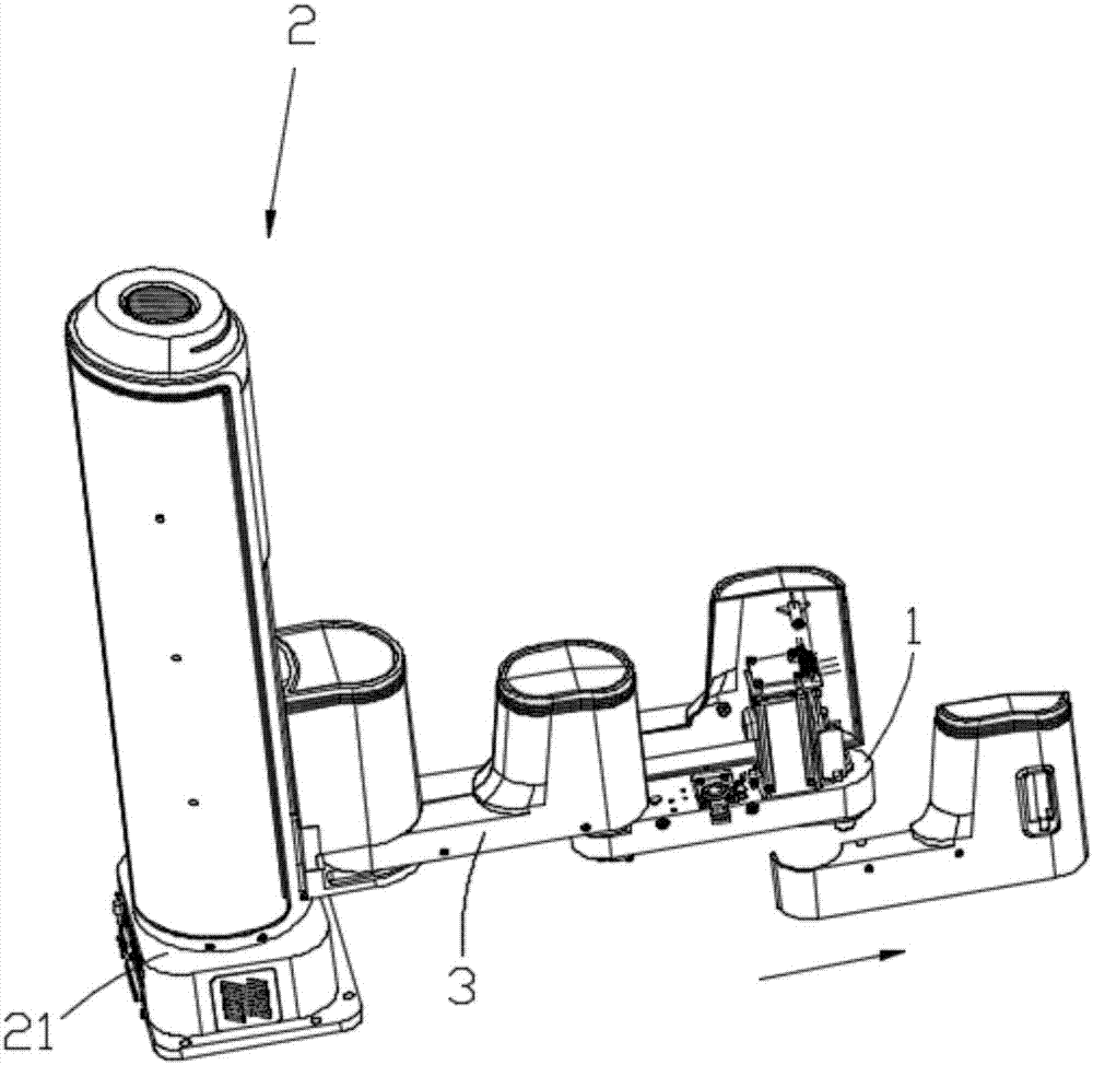
[0004] The purpose of the present invention is to provide a variable speed reduction device and a planar multi-joint robot, aiming at that the related motors in the prior art planar multi-joint robot can only output a fixed speed or output a variety of speeds, the control program is complicated, errors are easy to occur, etc. Shortcomings

Method used


Image

  • Speed changing and reducing device and plane multi-joint robot
  • Speed changing and reducing device and plane multi-joint robot
  • Speed changing and reducing device and plane multi-joint robot

Examples


Embodiment Construction

[0022] In order to make the objectives, technical solutions and advantages of the present invention clearer, the following further describes the present invention in detail with reference to the accompanying drawings and embodiments. It should be understood that the specific embodiments described herein are only used to explain the present invention, but not to limit the present invention.

[0023] In the description of the present invention, it should be understood that the terms "length", "width", "upper", "lower", "front", "rear", "left", "right", "vertical", The orientation or positional relationship indicated by "horizontal", "top", "bottom", "inner", "outer", etc. is based on the orientation or positional relationship shown in the drawings, and is only for the convenience of describing the present invention and simplifying the description, not It indicates or implies that the pointed device or element must have a specific orientation, be configured and operated in a specifi...


PUM


Abstract

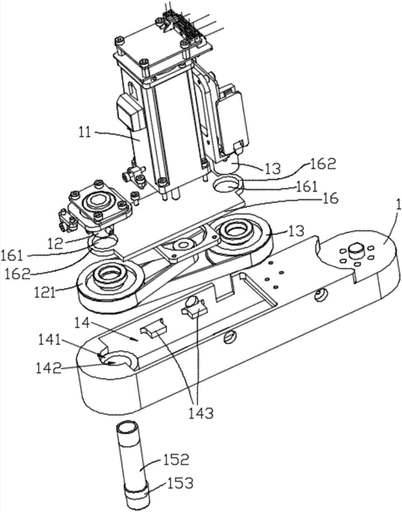
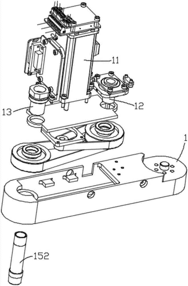
The invention relates to the technical field of automation, and discloses a speed changing and reducing device and a plane multi-joint robot. The speed changing and reducing device is arranged on anyjoint arm of the plane multi-joint robot. The joint arm is provided with a motor. The motor is provided with a rotation shaft. The speed changing and reducing device comprises an output shaft and an installing cavity formed in the extending direction of the joint arm, the installing cavity is internally provided with a base plate with multiple installing states, and the base plate is detachable. Abase is arranged on one side in the installing cavity and provided with a first installing hole. The base plate is provided with a motor and a plurality of transmission shafts, and transmission mechanisms are arranged between the transmission shafts and between at least one transmission shaft and the rotation shaft of the motor. The base plate is provided with a plurality of second installing holes, and the transmission shafts are arranged in the second installing holes and provided with installing bases. The speed changing and reducing device can output multiple rotation speeds on the premise that the position of the output shaft is not changed, and control program complex degree increasing and additional error generating are avoided.

Description

Technical field [0001] The technical field of automation involved in the present invention, in particular, relates to the end deceleration structure of a planar articulated robot. Background technique [0002] Planar multi-joint robot (scara robot) is a common robot structure in the field of automation. It generally has a vertical base on which a number of articulated arms (generally two: direct The big arm installed on the base and the small arm installed at the end of the big arm), each articulated arm can swing on a plane. The last articulated arm of the planar multi-joint robot is provided with an executive end, which can move longitudinally to realize spatial positioning and provide multiple functions such as automatic clamping, milling, 3D printing, and surgery. Planar articulated robots have the characteristics of mature structure, high degree of automation, easy control, etc., and more and more are replacing human hands in various fields to perform mechanized work. [000...

Claims


Application Information

Patent Timeline
Patent Type & Authority Applications(China)
IPC IPC(8): B25J9/10B25J9/06B25J17/00
CPCB25J9/06B25J9/102B25J17/00
Inventor 刘培超汪金星郎需林
Owner SHENZHEN YUEJIANG TECH CO LTD
Features
  • R&D
  • Intellectual Property
  • Life Sciences
  • Materials
  • Tech Scout
  • Unparalleled Data Quality
  • Higher Quality Content
  • 60% Fewer Hallucinations
Learn More