Flow guiding device, refueling component and refueling method

A diversion device and component technology, applied in distribution devices, special distribution devices, liquid distribution, transportation or transfer devices, etc., can solve problems such as business interruption, failure of terminal UPS system to operate normally, and unstable output voltage of generator sets. Achieve the effects of slowing down the liquid flow rate, compact structure, and convenient storage

Active Publication Date: 2019-04-26
TENCENT TECH (SHENZHEN) CO LTD
View PDF9 Cites 0 Cited by
  • Summary
  • Abstract
  • Description
  • Claims
  • Application Information

AI Technical Summary

Problems solved by technology

[0003] In the process of using diesel generators to generate electricity, the output voltage of the generators is prone to instability, resulting in the failure of the terminal UPS system to operate normally, resulting in business interruption

Method used


Image

  • Flow guiding device, refueling component and refueling method
  • Flow guiding device, refueling component and refueling method
  • Flow guiding device, refueling component and refueling method

Examples


Embodiment 1

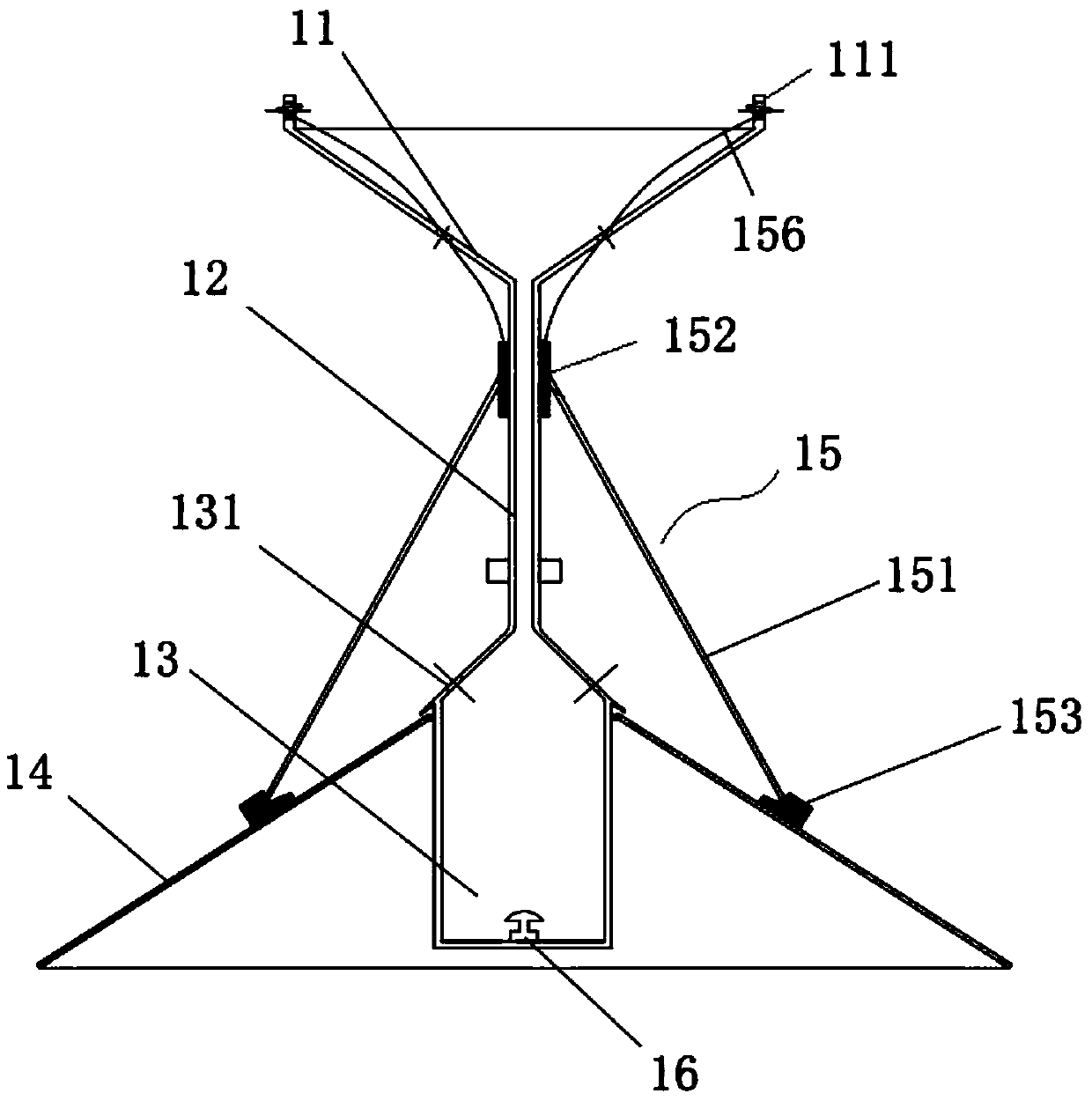
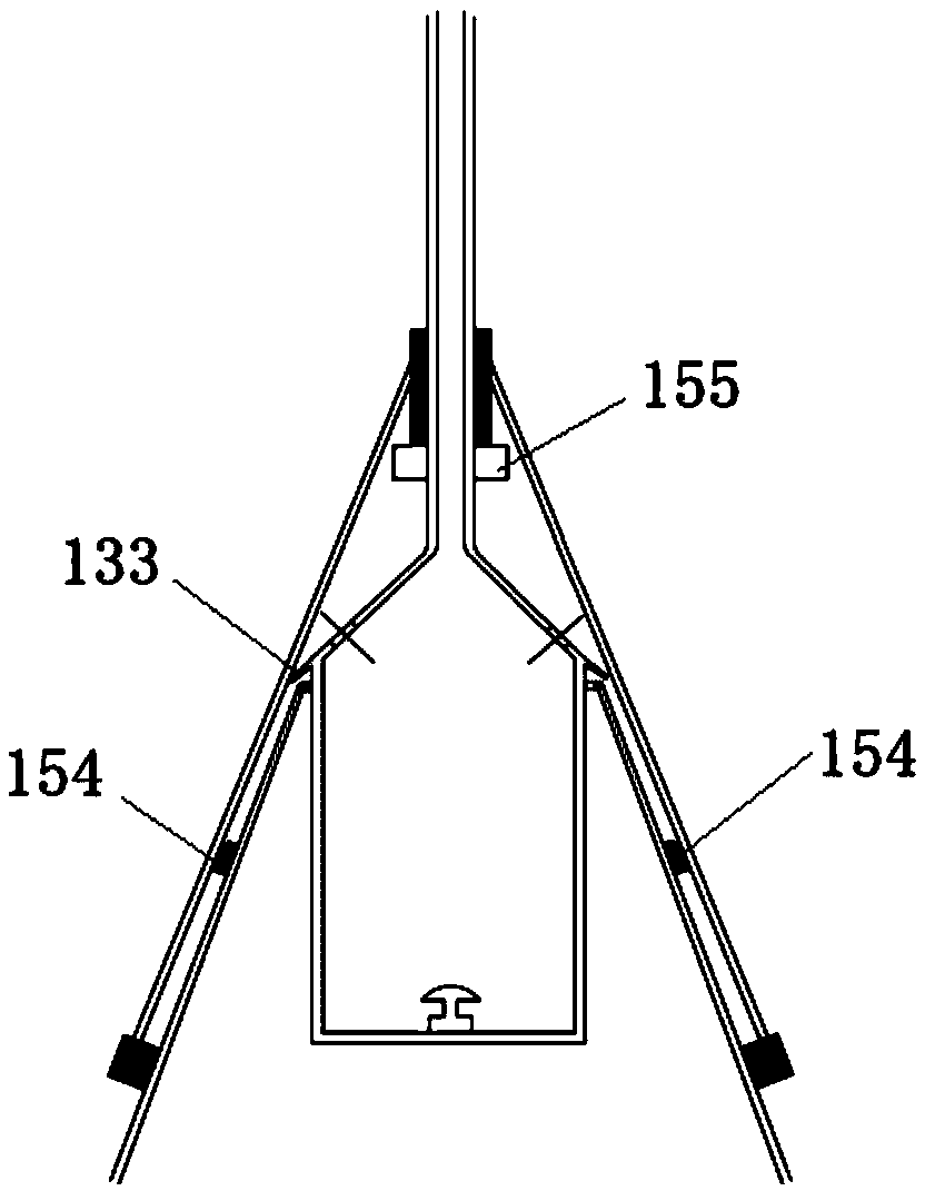
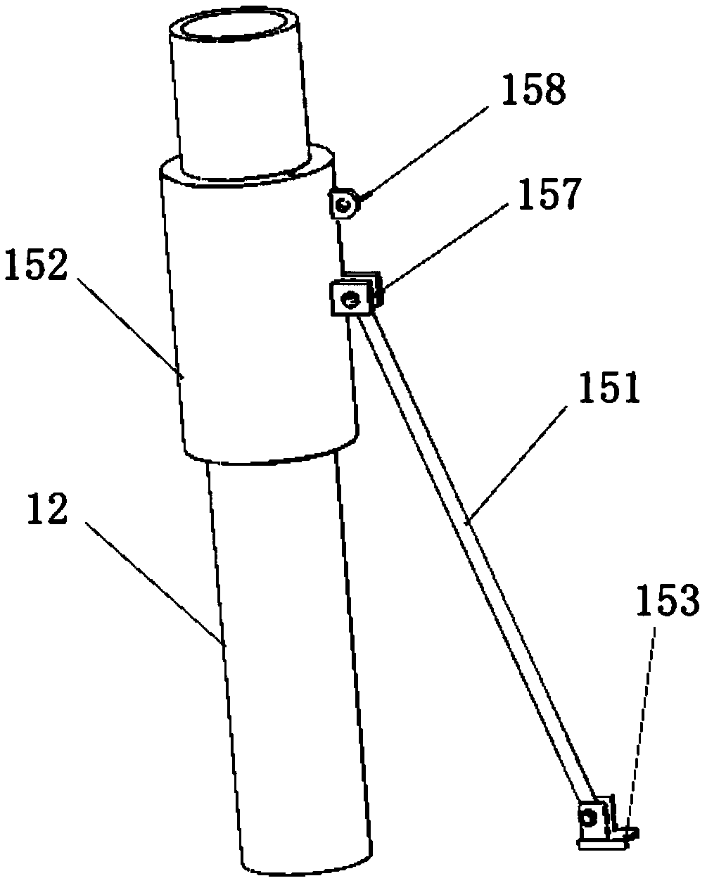
[0053] figure 1 It is a flow guiding device provided by the embodiment of the present invention, which can be used to guide the liquid when pouring liquid into the container, including: a partial pressure container 13, a flow guide tube 12, a flow divider 14 and a control mechanism 15, in,

[0054] The partial pressure container 13 is used for buffering the liquid, and a diversion hole 131 is opened on it;

[0055] The guide tube 12 communicates with the pressure dividing container 13, and is used to guide the liquid into the pressure dividing container 13;

[0056] The flow divider 14 is connected to the outer wall of the pressure dividing container 13, and the flow divider 14 has a distributing surface 142 that can be expanded or folded, and the flow dividing surface 142 is used to guide the liquid overflowing from the diversion hole 131 of the pressure dividing vessel to flow out smoothly ;

[0057] The control mechanism 15 is used to control the expansion or contraction...

Embodiment 2

[0074] Figure 7 It is a structural schematic diagram of a refueling assembly provided by an embodiment of the present invention. see Figure 7 , a refueling assembly with a flow guide device, including a refueling pump 27, a controller 28, a fuel delivery pipe 29 and a flow guide device. Wherein, the oil delivery pipe 29 is connected with the output port of the refueling pump 27, and is used for delivering the fuel pressurized by the refueling pump 27 to the diversion device; the controller 28 is used for automatically adjusting the fuel pump 27 according to the liquid level information sent by the diversion device Oil intake.

[0075] Specifically, the flow guiding device includes a pressure dividing container 23 , a flow guiding tube 22 , a flow divider 24 , a control mechanism 25 and a liquid level detector 26 . The guide pipe 22 communicates with the pressure-dividing container, and is used to guide the fuel into the pressure-dividing container 23 . The pressure-divid...

Embodiment 3

[0092] Figure 10 It is a flow chart of a refueling method provided by an embodiment of the present invention. The refueling method is completed using the refueling assembly in Embodiment 2, including:

[0093] S101. Install the flow guide device at the opening of the oil storage container, and expand the flow diversion surface of the flow divider.

[0094] S102. Move the oil delivery pipe until the outlet of the oil delivery pipe is opposite to the inlet of the draft pipe.

[0095] S103. Start the refueling pump, use the refueling pump to pressurize the fuel, the pressurized fuel enters the pressure dividing container through the fuel delivery pipe and the diversion pipe, overflows from the diversion hole on the pressure dividing container, and smoothly flows into the storage tank along the diversion surface of the diverter oil container.

[0096] As an optional method, installing the flow guiding device at the opening of the oil storage container, and expanding the flow di...


PUM


Abstract

The invention provides a flow diversion device which is used for pouring liquid into a container. The flow diversion device comprises a partial pressure container, a flow diversion pipe, a flow divider, and a controlling mechanism. The guiding flow duct communicates with the partial pressure container to guide liquid into the partial pressure container; the partial pressure container is used for slowly saving fuel oil and is provided with a flow diversion hole; the flow divider is connected with the outer wall of the partial pressure container and comprises a flow diversion face used for the guiding fuel oil spilling from the flow diversion hole of the partial pressure container to outflow flatly; the controlling mechanism is used for controlling the flow diversion face to be open up or close up. The flow diversion device use the partial pressure container to slow down the surge pressure of the liquid to further use the flow divider to increase a flow diversion area and to slow down liquid flow rate, so that the liquid can evenly and slowly flow into the container. The flow diversion device has advantages that the structure is compact, storage is convenient, application range is wide. In addition, the invention also provides a refueling assembly and a refueling method of the flow diversion device.

Description

technical field [0001] The invention relates to the fields of electrical engineering and power, in particular to a deflector, a refueling component and a refueling method thereof. Background technique [0002] During the operation of the data center computer room, the diesel generator set is used as a backup power supply system, which needs to be put into use quickly in case of power interruption or abnormality, so as to provide continuous and reliable power supply to the computer room and avoid risks caused by business interruption. In the process of using diesel generator set to generate electricity, diesel oil needs to be delivered to the oil storage tank. The existing refueling method is: use a fuel pump to pressurize the diesel oil, and then deliver the diesel oil to the oil storage tank through the oil delivery pipe. The stable voltage output of the front-end diesel generator set is conducive to maintaining the normal operation of the terminal UPS (Uninterruptible Powe...

Claims


Application Information

Patent Timeline
Patent Type & Authority Patents(China)
IPC IPC(8): B67D7/78B67D7/04
CPCB67D7/04B67D7/78
Inventor 卢卓嘎郁智华李潘冷情黄永军刘垚李智捷李宇明王鹏葛玮
Owner TENCENT TECH (SHENZHEN) CO LTD
Why Eureka
Try Eureka