
Composite structure energetic container

A composite structure and container technology, applied in the direction of pressure vessels used in chemical processes, etc., can solve the problems of inability to meet large-scale production, short service life of energy-containing containers, easy deformation of energy-containing containers, etc., and achieve easy installation and maintenance. The effect of mass production and longevity

Active Publication Date: 2016-05-11
PENG CARBON TECH
View PDF13 Cites 2 Cited by
  • Summary
  • Abstract
  • Description
  • Claims
  • Application Information

AI Technical Summary

Problems solved by technology

[0006] Due to the existence of high pressure and high temperature (pressure reaches 5-6 MPa, temperature reaches 2100 degrees Celsius) in the energetic container, and there are structural defects in the existing energetic container, the existing energetic container is usually a single-layer structure. The material of the layer shell includes carbon steel, composite steel or titanium steel. At the moment of energetic reaction, because the spherical shell is a single-layer structure, the shell is relatively weak, the load-bearing strength is low, and the lack of impact reduction device makes the energetic container easy to Deformation, or even damage to the shell of the container at the moment of the energetic reaction, so that the existing energetic container has a short service life and cannot meet the needs of large-scale production. Therefore, those skilled in the art urgently need to provide a new type of energetic container to solve the above problems

Method used


Image

  • Composite structure energetic container
  • Composite structure energetic container

Examples


Embodiment Construction

[0025] In order to make the content of the present invention clearer and easier to understand, the content of the present invention will be further described below in conjunction with the accompanying drawings of the specification. Of course, the present invention is not limited to this specific embodiment, and general replacements well known to those skilled in the art are also covered by the protection scope of the present invention. Secondly, the present invention uses schematic diagrams to describe in detail. When describing the examples of the present invention, for convenience of explanation, the schematic diagrams are not partially enlarged according to the general scale and should not be used as a limitation to the present invention.

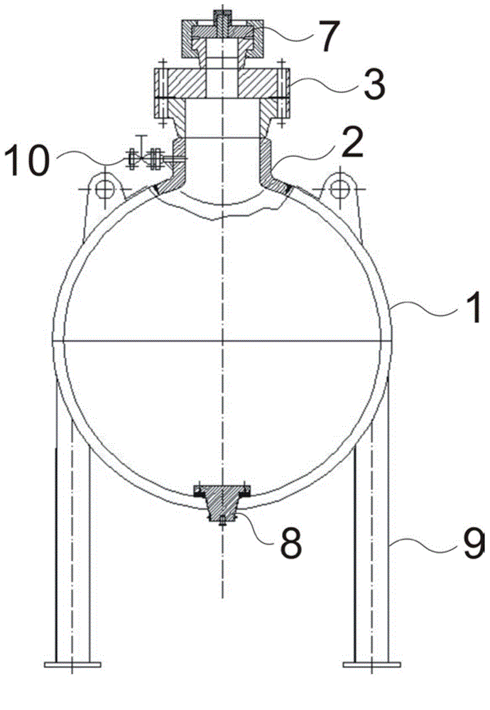
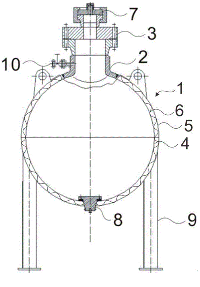
[0026] See figure 2 , figure 2 It is a schematic structural diagram of an energy-containing container with a composite structure of the present invention.

[0027] Such as figure 2 As shown, the present invention provides an energy-cont...


PUM


Abstract

The invention discloses a composite structure energetic container, which includes a hollow spherical shell with openings at the upper end and lower end. The shell consists of: an inner shell, an outer shell and a buffer device fixed between the inner shell and the outer shell. Specifically, the buffer device is a steel plate with a continuous wavy section, the wave bottom of the wavy steel plate is in fixed connection with the inner shell, and the wave top of the wavy steel plate is in fixed connection with the outer shell. According to the invention, through setting of the composite structure shell, the compression resistance and bearing strength of the energetic container shell are enhanced, the surge pressure of the reaction moment is buffered, and the life and the quality of the energetic container are improved. In addition, the composite structure energetic container provided by the invention also has the advantages of convenient installation, high reliability, easy installation and maintenance, etc., greatly improves the service life of the energetic container, and meets the needs of mass production.

Description

Technical field [0001] The invention relates to the field of energetic materials, and more specifically, to an energetic container with a composite structure. Background technique [0002] Energetic materials are mainly divided into three categories: explosives, propellants and pyrotechnic agents according to their uses. They play a pivotal role in civil, military and aerospace fields. They are special functional materials that have been used on a large scale. Nowadays, with the development and progress of nanotechnology, many new concepts are prepared by energetic materials. [0003] Take three-dimensional graphene coated single-particle nanodiamond as an example. Graphene is a two-dimensional hexagonal lattice honeycomb structure composed of a single layer of SP2 hybrid carbon atoms. It has a stable structure, excellent electrical and thermal conductivity, and good mechanical properties. , Which has been extensively studied. Graphene has been prepared and used in energy storage...

Claims


Application Information

Patent Timeline
Patent Type & Authority Applications(China)
IPC IPC(8): B01J3/04
Inventor 彭雁杜桂香
Owner PENG CARBON TECH
Learn More