Structure for preventing and reducing hazard of retention air mass in deep regulation and storage tunnel
A tunnel and air mass technology, which is applied in drainage, mining equipment, safety devices, etc., can solve the problems of high cost, unable to solve the problem of trapped air mass in the main body of the deep tunnel, and the damage of the inner wall structure of the tunnel, and achieve the effect of mitigating the impact
- Summary
- Abstract
- Description
- Claims
- Application Information
AI Technical Summary
Problems solved by technology
Method used
Image

Examples
Embodiment Construction
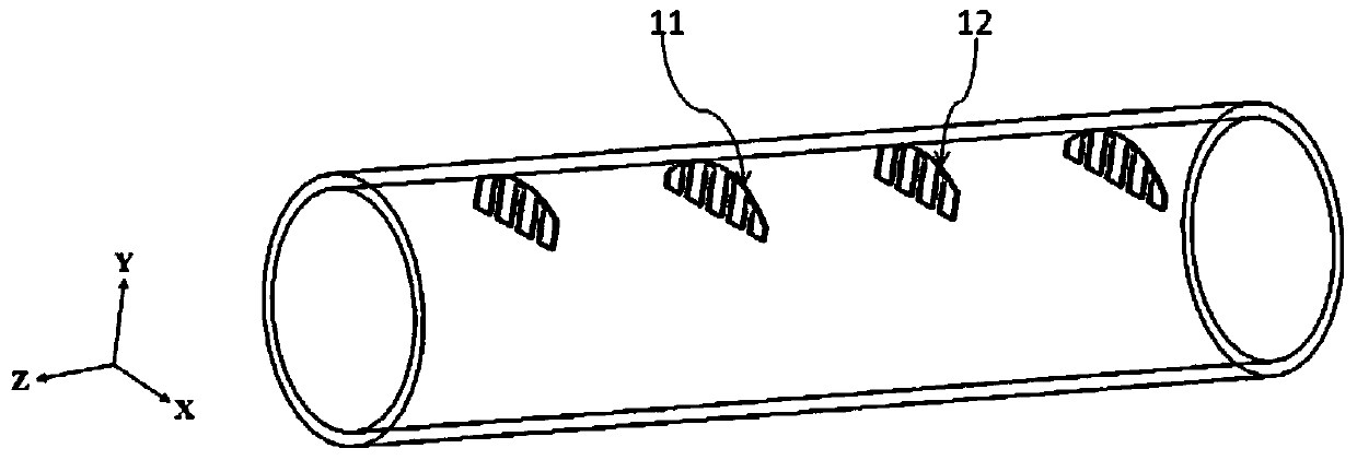
[0020] The present invention will be described in further detail below in conjunction with the accompanying drawings. The following examples are only used to illustrate the technical solution of the present invention more clearly, but not to limit the protection scope of the present invention. The axis described in the present invention is figure 1 The direction of the Z axis, the height direction described in the present invention is along figure 1 In the direction of the Y axis, the width direction described in the present invention is along the figure 1 The direction of the X-axis.
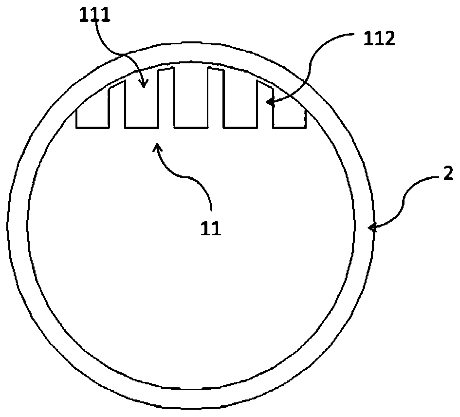
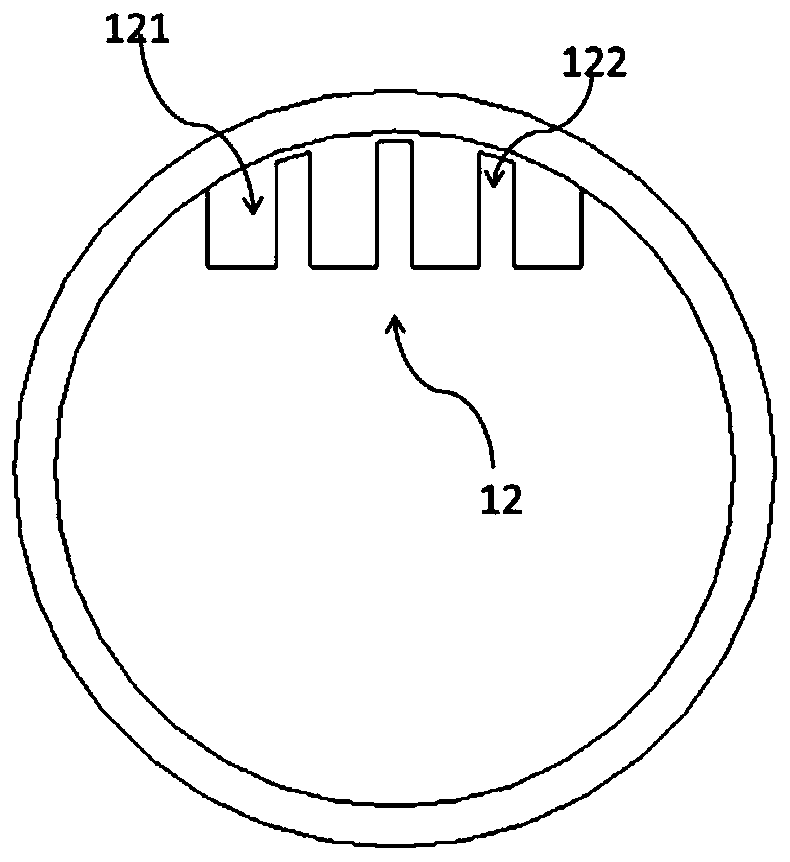
[0021] Such as figure 1 As shown in the present invention, a structure for preventing and reducing the hazards of trapped air masses in deep regulation and storage tunnels is composed of several baffle assemblies 1 installed vertically on the top of the pipe wall of the deep tunnel 2. The density is low, and the gas will go to the top of the deep tunnel. The baffle assembly 1 is installed o...
PUM
 Abstract
Description
Claims
Application Information