a keyboard

一种键盘、键帽的技术,应用在电气元件、触觉反馈、层等方向

Active Publication Date: 2019-08-27
DARFON ELECTRONICS (SUZHOU) CO LTD +1
View PDF8 Cites 0 Cited by
  • Summary
  • Abstract
  • Description
  • Claims
  • Application Information

AI Technical Summary

Problems solved by technology

[0003] In order to improve the above noise problem, the present invention provides a keyboard

Method used


Image

  • a keyboard
  • a keyboard
  • a keyboard

Examples


Embodiment Construction

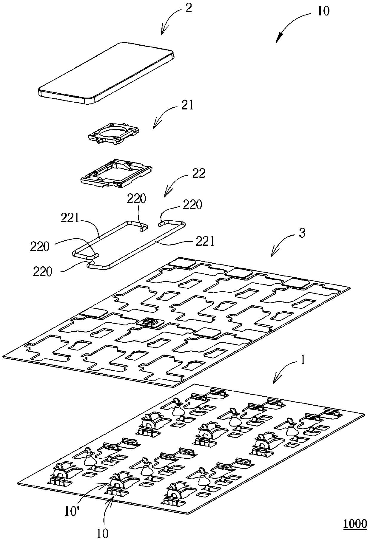
[0115] The directional terms mentioned in the following embodiments, such as: up, down, left, right, front or rear, etc., are only for referring to the directions of the attached drawings. Accordingly, the directional terms used are illustrative and not limiting of the present invention. see figure 1 , figure 1 It is a schematic diagram of the appearance of the first embodiment of the keyboard of the present invention. like figure 1 As shown, the keyboard 1000 includes a base plate 1 and a plurality of multiple keys 2 (such as Caps Lock, Shift, and Enter keys on a general standard keyboard) whose left and right widths are much larger than the front and rear dimensions. The plurality of keys 2 are arranged on the base plate 1 and used to execute Key commands, such as input characters, numbers, symbols, etc.

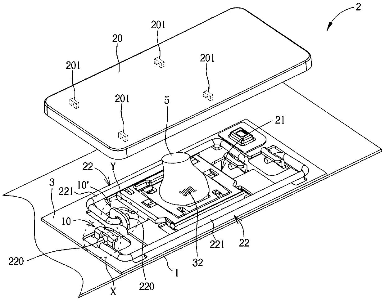
[0116] see figure 2 , figure 2 It is a partial exploded schematic diagram of one of the keys in the first embodiment of the keyboard of the present invention. lik...


PUM


Abstract

The invention relates to a keyboard which achieves a noise reduction effect via a buffer layer, sheet or piece. The buffer layer is arranged on a clamping structure of a base plate and makes real contact with the linkage end portion of a balancing rod to buffer collision between the linkage end portion and a clamping hole of the clamping structure; the buffer sheet is arranged on the clamping structure, and the wall of a limiting hole in the buffer sheet buffers collision between the linkage end portion and the wall of the clamping hole; and the buffer piece is connected to one selected from a circuit board, a connecting thin layer, the base plate and a backlight module, the linkage end portion of the balancing rod moves in the limiting hole in the buffer sheet correspondingly, and the material of the buffer piece is softer than that of the base plate. Thus, the buffer layer, sheet and piece can be used to reduce collision sound emitted when the linkage end portion moves relative to the base plate.

Description

technical field [0001] The present invention relates to a keyboard, in particular to a keyboard with noise reduction effect. Background technique [0002] Generally speaking, a keyboard is equipped with a plurality of key devices for the user to press to generate an input signal, so that the user can use the plurality of key devices to input characters, numbers, symbols and the like. For some specific buttons, such as the Caps Lock button, a link bar may be provided to support the keycap of the button device to move up and down relative to the bottom plate, and in the prior art, the link between the support bar and the bottom plate is usually a shaft (Shaft) - Holes (holes) are fitted, and there is usually a gap between the shaft holes. Therefore, when the key device is pressed, the above-mentioned shaft member and the hole wall of the hole often collide with each other to generate noise. SUMMARY OF THE INVENTION [0003] In order to improve the above-mentioned noise pro...

Claims


Application Information

Patent Timeline
Patent Type & Authority Patents(China)
IPC IPC(8): H01H13/704H01H13/84
CPCH01H13/02H01H13/70H01H13/704H01H13/705H01H13/7065H01H13/84H01H2209/052H01H2215/03
Inventor 廖本辉林钦宏林彦孝刘信鸿郑家福
Owner DARFON ELECTRONICS (SUZHOU) CO LTD
Why Eureka
Try Eureka