Gravity drain valve

a gravity drain and valve body technology, applied in the field of gravity drain valves, can solve the problems of corroding drain pipes, urine is highly corrosive, and the risk of infection and potential disease transmission is increasing, and achieves the effect of reducing manufacturing and assembly costs and softer materials

Active Publication Date: 2015-10-22
NWS EUROPA
View PDF4 Cites 15 Cited by
  • Summary
  • Abstract
  • Description
  • Claims
  • Application Information

AI Technical Summary

Benefits of technology

[0012]According to yet another example embodiment there is provided a drain valve support comprising a rigid post member having an engagement formation for attachment to a drain valve support structure. The post member has one or more membranes in the form of a skirt molded thereon such that the skirt valve is fused or otherwise integrally formed onto post member, the skirt valve being of a softer material than the post and a major cost savings in manufacturing and assembly.

Problems solved by technology

Furthermore, they can expose individuals to airborne contaminants or, in the case of back-flow, water-borne contaminants, thereby increasing the risk of infection and potential disease transmission.
It is a known fact that urine is highly corrosive and if not flushed periodically with water, it can corrode drain pipes.
However, this consumes significant volumes of liquid, which represents an inefficient and wasteful use of available water resources.
In the event that an open drain is flushed or washed less regularly, the drain can become unsanitary and the odor emanating from the drain can attract unwanted insects and vermin to its vicinity.
More recent trends towards chemical or ‘dry’ cleaning mean that the drain is more susceptible to debris retention and clogging.
In the event that a drain trap is used, clogging is particularly problematic and can quickly block the drain.
However, such examples are typically bulky, such that they are not well suited to a retro-fit of existing drains, as well as being expensive to manufacture.
The use of chemicals means that the device requires frequent replacement, such that the ongoing cost to an end user is significant.
Also, the chemical is a known pollutant and so the disposal of the chemical within such devices represents a major and costly undertaking at the water reclamation center.
However, the available static flow area of those valves and the weight of liquid required to actuate the valve member into its open condition cause potential problems.
For example, a volume liquid may be retained above the valve member for extended periods of time, which can in itself be odorous or otherwise unsanitary.
In some instances solids like cigarettes butts, tooth picks, mop strings and sand can catch on the hinge member causing the valve to stay in the open position for long period of time.
Furthermore, the maximum flow rate permitted through the above examples of prior art valves is limited by the valve design and construction and may be insufficient to accommodate rapid flushing do to its narrow valve inside opening or, particularly in the case of ground drains, flooding.
The inventor has also found that the provision of a mechanical valve at a drain opening can cause further problems.
More specifically, the movement of fluid within a drain system can cause pneumatic pressure within the drain and, in the case of drain backflow, hydraulic pressure at the drain opening.
This can lead to the build-up of excessive pressure within the drain, which may in itself be problematic for correct drain function, and which can in turn cause the drain valve to deform and / or become unseated, thereby preventing correct operation once the back-pressure is relieved.

Method used


Image

  • Gravity drain valve
  • Gravity drain valve
  • Gravity drain valve

Examples


Embodiment Construction

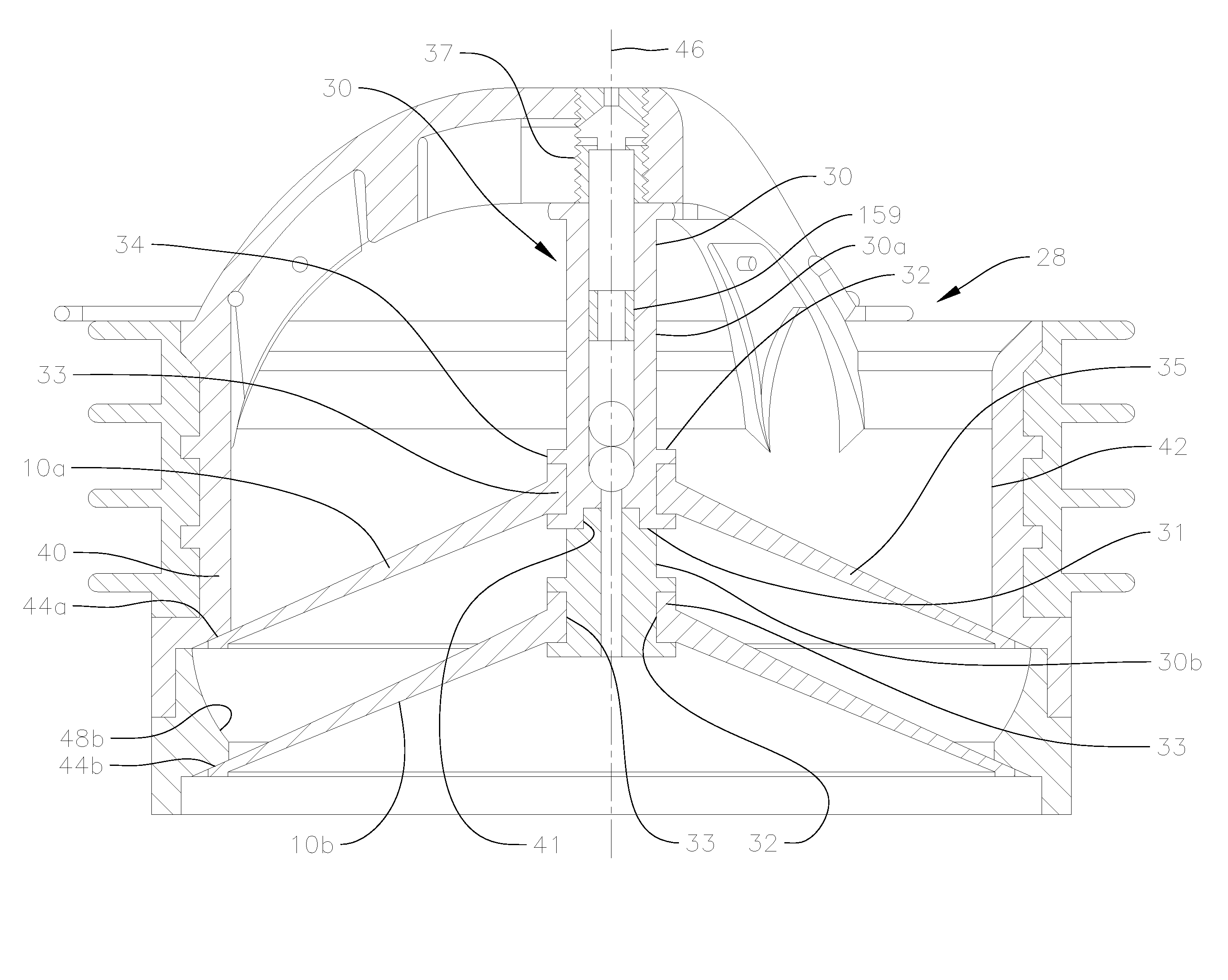
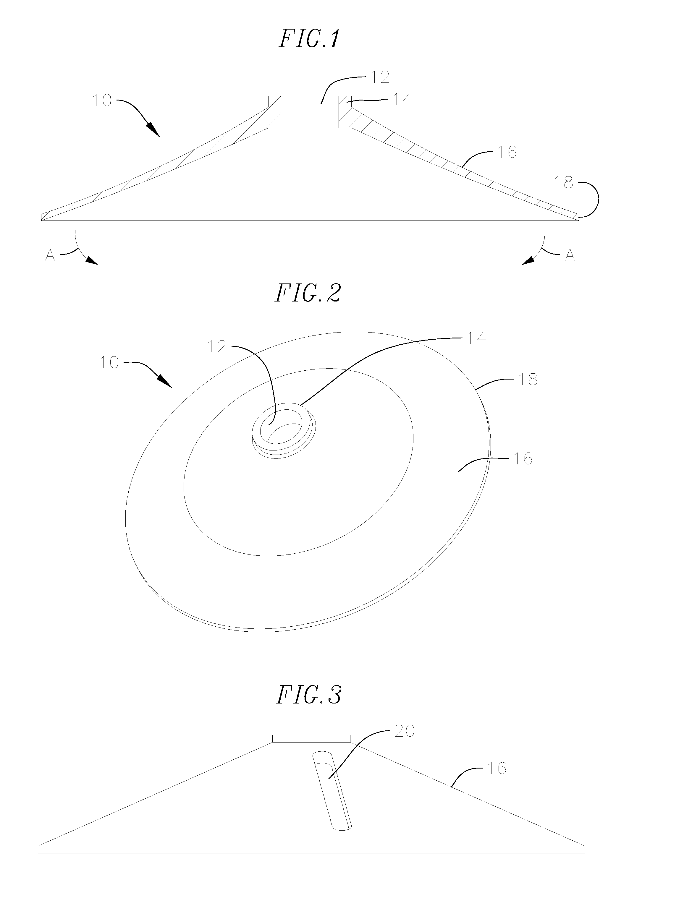
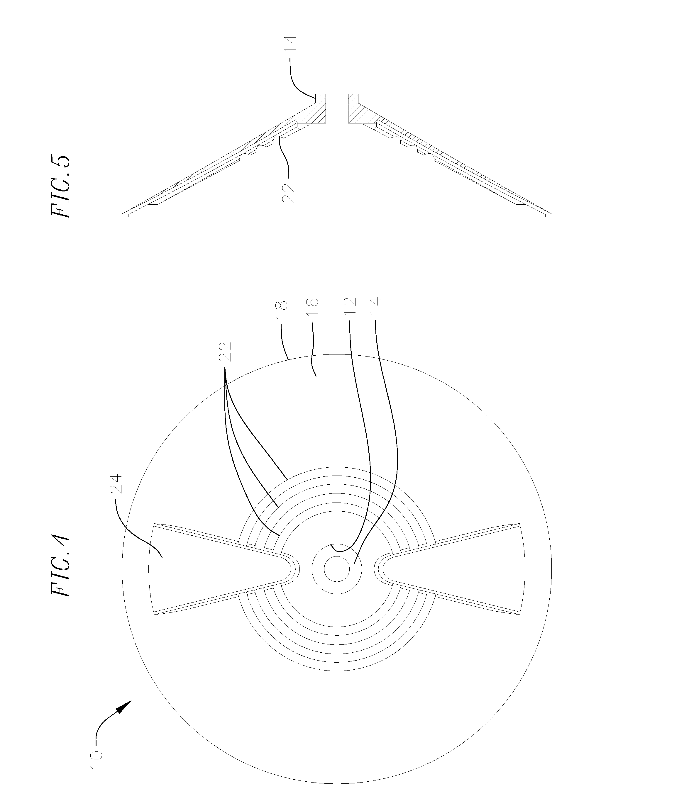
[0049]The following description sets out in different sections the different structural components and functions for a number of high flow and / or pressure venting gravity drain valve arrangements. Since the present disclosure comprises numerous developments over existing drain valves, it will be understood that different combinations of structural components and features from the different sections of this disclosure may be combined in ways other than those shown explicitly in the accompanying figures. Accordingly, the scope of the invention is to be defined by the accompanying claims and may accommodate any such combinations of features wherever practicable, whether or not a particular combination is explicitly disclosed herein. It is to be understood by the reader that features of smaller diameter drain valves, such as for urinals, sinks, baths and the like may be applied to larger drain valves, such as floor / ground drain valves, and vice-versa, wherever beneficial.

[0050]Valve Mem...


PUM


Abstract

A drain valve device includes a drain valve housing arranged to be located within a drain opening. The housing has a wall structure surrounding an axis so as to define an internal flow passage through the housing and a strut member depending radially inwardly from the wall structure. The device has one or more valve members. A gas vent passage may be provided in the housing and a vent valve or control member may be provided to selectively prevent flow through the gas vent passage.

Description

CROSS-REFERENCE TO RELATED APPLICATION(S)[0001]This application is based upon and claims priority on U.S. Provisional Application Ser. No. 61 / 995,846, filed on Apr. 22, 2014 and titled “FLOOR DRAIN VALVE AND WATER FLUSH URINALS GRAVITY VALVE WITH AUTOMATIC VENTING SYSTEM,” the contents of which are fully incorporated herein by reference.BACKGROUND OF THE INVENTION[0002]This disclosure concerns drain valves in which fluid can flow down a drain under the action of gravity. More particularly, this disclosure concerns drain valves for location in a liquid outflow from a urinal, sink, floor drain or the like. Open gravity drains allow escape of odorous gas or vapor into the surrounding air. Furthermore, they can expose individuals to airborne contaminants or, in the case of back-flow, water-borne contaminants, thereby increasing the risk of infection and potential disease transmission. It is a known fact that urine is highly corrosive and if not flushed periodically with water, it can co...

Claims


Application Information

Patent Timeline
Patent Type & Authority Applications(United States)
IPC IPC(8): F16K15/14E03C1/298
CPCE03C1/298F16K15/148E03D13/007F16K24/042F16K27/0209F16K31/1268
Inventor FIMA, GIOVANNI
Owner NWS EUROPA
Why Eureka
Try Eureka