
Terminal housing and terminal

A terminal shell and shell technology, which is applied in specific array feeding systems, antenna grounding devices, and structural forms of radiation elements, can solve problems such as small clearance areas, reduce contact points, reduce space, and save costs. Effect

Active Publication Date: 2018-04-06
BEIJING XIAOMI MOBILE SOFTWARE CO LTD
View PDF11 Cites 4 Cited by
  • Summary
  • Abstract
  • Description
  • Claims
  • Application Information

AI Technical Summary

Problems solved by technology

[0004] However, as terminal functions become more diverse and complex, more and more components need to be installed inside the terminal body, making the clearance area inside the terminal body for designing antennas smaller and smaller

Method used


Image

  • Terminal housing and terminal
  • Terminal housing and terminal
  • Terminal housing and terminal

Examples


Embodiment Construction

[0039] In order to make the purpose, technical solution and advantages of the present disclosure clearer, the implementation manners of the present disclosure will be further described in detail below in conjunction with the accompanying drawings.

[0040] Reference will now be made in detail to the exemplary embodiments, examples of which are illustrated in the accompanying drawings. When the following description refers to the accompanying drawings, the same numerals in different drawings refer to the same or similar elements unless otherwise indicated. The implementations described in the following exemplary examples do not represent all implementations consistent with the present disclosure. Rather, they are merely examples of apparatuses and methods consistent with aspects of the present disclosure as recited in the appended claims.

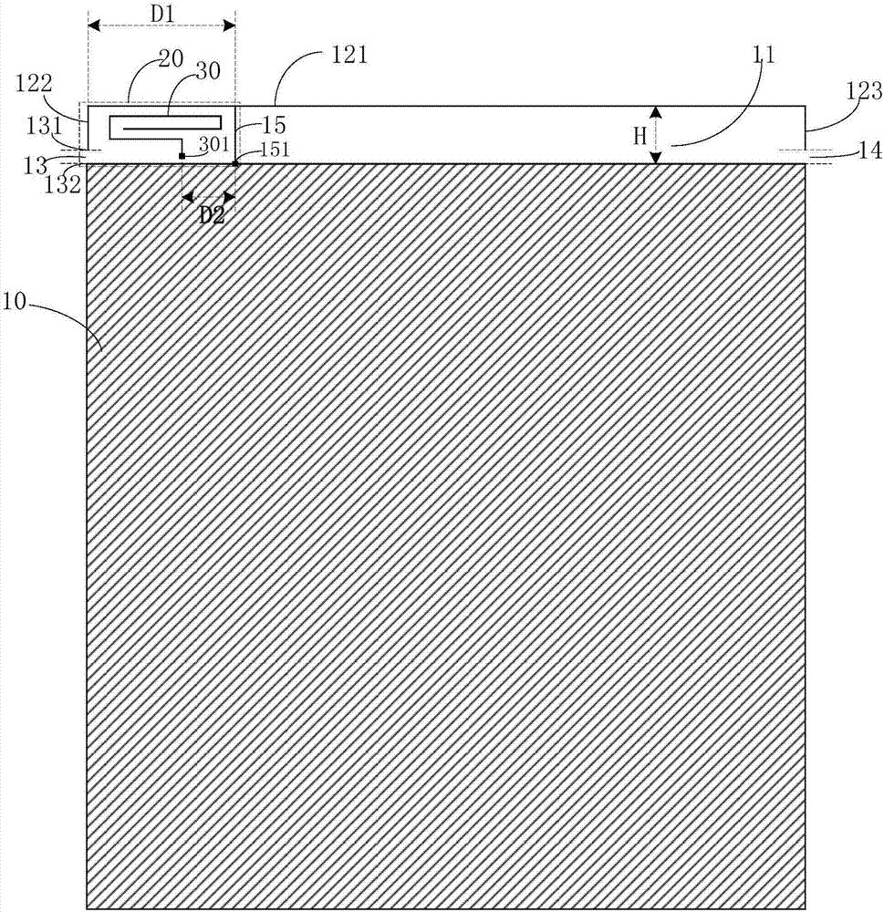
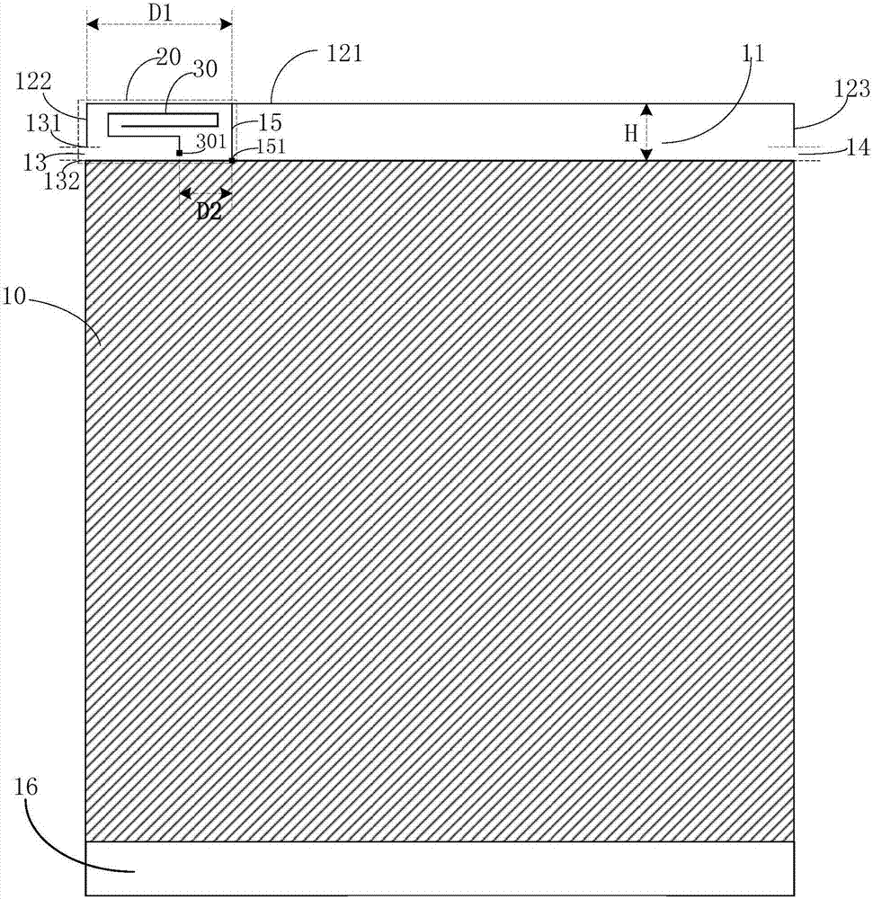
[0041] Figure 1A is a rear view of a terminal housing shown according to an exemplary embodiment, see Figure 1A , the terminal housing i...


PUM


Abstract

The present disclosure provides a terminal housing and a terminal and belongs to the terminal technical field. The terminal housing comprises a lower all-metal shell and an upper non-metal shell; theouter edge of the upper non-metal shell is wrapped with a metal frame; a first gap is left between the first side border of the metal frame and the side edge of the lower all-metal shell; the upper non-metal shell is provided with a vertical metal line; the first end of the vertical metal line is a grounding point; the second end of the vertical metal line is connected with the top border of the metal frame; and a portion between the first end of the vertical metal line and the upper edge of the first gap forms a first antenna stub; a second antenna stub of a bend line structure is disposed between the first side border and the vertical metal line; and one end of the second antenna stub is a feed point. According to the terminal housing and the terminal of the invention, the gap is formedat the side border of the terminal housing; the metal frame is adopted as a part of the antenna of the terminal; the antenna is designed to be of a bend line structure, so that a space occupied by theantenna can be decreased; and the limited clearance zone of the terminal can be utilized to design the antenna.

Description

technical field [0001] The present disclosure relates to the technical field of terminals, and in particular, to a terminal casing and a terminal. Background technique [0002] With the development of terminal technology and the change of aesthetic standards of users, it has become a popular trend to design the back cover of the terminal as a metal back cover. [0003] In the related art, the terminal antenna is usually set in the clear area inside the terminal. In order to prevent the terminal back cover from shielding the terminal antenna, so that the terminal cannot send and receive signals normally, the terminal back cover is usually designed in three sections. There is a gap between them, so that the terminal antenna can receive and send signals through the gap opened. [0004] However, as terminal functions become more diverse and complex, more and more components need to be installed inside the terminal body, making the clearance area inside the terminal body for des...

Claims


Application Information

Patent Timeline
Patent Type & Authority Applications(China)
IPC IPC(8): H01Q1/36H01Q1/44H01Q1/48H01Q1/50H01Q21/00H01Q21/30
CPCH01Q1/36H01Q1/44H01Q1/48H01Q21/0006H01Q21/30
Inventor 王霖川薛宗林熊晓峰
Owner BEIJING XIAOMI MOBILE SOFTWARE CO LTD
Learn More