A method and device for increasing the output current peak factor of an inverter

A technology of output current and crest factor is applied in the field of improving the peak factor of the output current of the inverter, which can solve the problems affecting the quality of the output voltage waveform of the inverter and the temperature rise of the inverter tube transformer, so as to improve the FA and increase the output current. The effect of the crest factor

Active Publication Date: 2019-10-01
ZHANGZHOU KEHUA ELECTRIC TECH CO LTD
View PDF8 Cites 0 Cited by
  • Summary
  • Abstract
  • Description
  • Claims
  • Application Information

AI Technical Summary

Problems solved by technology

The output current peak factor is an index to measure the nonlinear load capacity of UPS. If FA=3 is designed during the design process, then when the inverter drives the nonlinear load with FA=3 to overload, or when the inverter drives FA> 3, the phenomenon of inverter output current limiting will appear; the inverter output current limiting will affect the waveform quality of the inverter output voltage, and even the temperature of the inverter tube or transformer will be caused by the current limiting action. rise rapidly

Method used


Image

  • A method and device for increasing the output current peak factor of an inverter
  • A method and device for increasing the output current peak factor of an inverter
  • A method and device for increasing the output current peak factor of an inverter

Examples


Embodiment 1

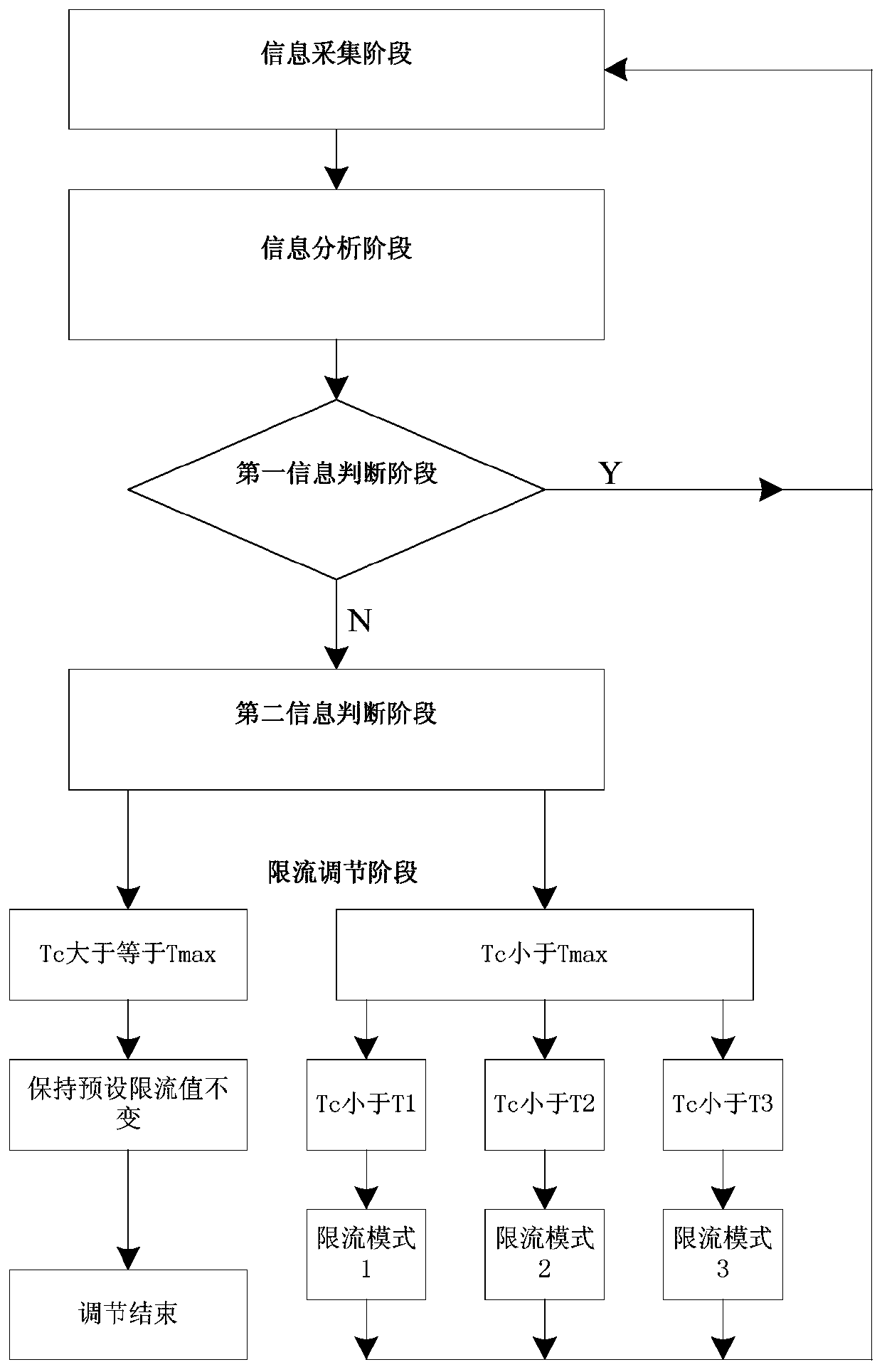
[0037] refer to figure 1 , a method for increasing the peak factor of the output current of the inverter, comprising the following steps:

[0038] 1) Information collection stage, which includes the collection of two pieces of information: ① detecting the peak output current I of the inverter p ; ② Acquisition hardware circuit inverter output current limiting signal I ov ;

[0039] 2) Information analysis stage, which includes two parallel analysis sub-steps, ① judging the output current peak value I of the inverter p Has reached the preset inverter current limit value I set ; ② judge inverter output current limiting signal I ov Whether it is a high-level signal; the inverter outputs the current-limiting signal I ov means: when the peak output current I of the inverter p When the preset inverter current limit value has been reached, the controller outputs a high-level inverter output current limit signal I ov ;

[0040] 3) In the first information judgment stage, in th...

Embodiment 2

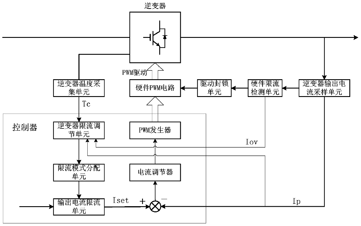
[0053] refer to image 3 , a device for increasing the output current peak factor of an inverter, comprising:

[0054] Controller: It has a built-in inverter current-limiting adjustment unit, and its preset inverter current-limiting value I set ;

[0055] Inverter output current sampling unit, the inverter collector output current value sampled by it is transmitted to the controller, and the peak value of the inverter output current value is compared with the preset inverter current limit value I set compare; if I p ≥I set , then judge the peak output current I of the inverter p The preset inverter current limit value I has been reached set ; Concretely, there is a comparison unit in the controller, and the output current peak value I of the inverter is p with the preset inverter current limit value I set Subtraction, if the result is a negative number, the current regulator and the PWM generator drive the hardware PWM circuit to stop outputting the PWM drive signal to ...


PUM


Abstract

The present invention provides a method of improving the peak coefficient of the output current of the inverter, including the following steps: 1) Judging the peak of the output current of the inverter p Whether it has reached the preset inverter restriction value i set , If you turn into step 2, if you continue to execute step 1; 2) the temperature T c And the current limit adjustment temperature valve value T max The size; the temperature valve value T max It refers to the preset inverter restricted flow value i set The corresponding inverter temperature; when the temperature T of the inverter c Higher than T max At the same time, the maximum current I can withstand the hub IGBT IGBT IgBT I cmax Smaller than the preset inverter restricted value; when T c << max At the same time, the preset inverter restricted flow value i set Raise; c ≥ t max At the same time, the preset inverter restricted flow value i set constant.The present invention also provides a device that improves the peak coefficient of the output current of the inverter.

Description

technical field [0001] The invention relates to an inverter, in particular to a method and a device for improving the output current peak factor of the inverter. Background technique [0002] The output current peak factor FA is the basic index of the inverter, which requires the output current peak factor FA≥3, which is defined as: UPS in normal working mode, the output is connected to a nonlinear load, and the UPS reaches the rated output capacity, and the adjustment Non-linear load peak current, and maintain the output rated capacity of the UPS, use a power harmonic analyzer to measure the peak IP and effective value IA of the UPS output current, and the output current peak factor FA=IP / IA. The peak factor of the output current is an index to measure the nonlinear load capacity of the UPS. If FA=3 is designed during the design process, then when the inverter drives the nonlinear load with FA=3 to overload, or when the inverter drives FA> 3, the phenomenon of inverter ...

Claims


Application Information

Patent Timeline
Patent Type & Authority Patents(China)
IPC IPC(8): H02M1/32
CPCH02M1/32H02M1/325H02M1/327
Inventor 苏先进崔福军陈坤裕林高达赖永春
Owner ZHANGZHOU KEHUA ELECTRIC TECH CO LTD
Why Eureka
Try Eureka