Fast power detector

a detector and fast technology, applied in electrical equipment, orthogonal multiplexes, digital transmission, etc., can solve the problems of increasing complexity and price, power amplification units, and risking the destruction of power amplification units, so as to minimize complexity and costs of information signal communication devices, and high crest factor

Inactive Publication Date: 2007-11-08
HARRIS CORP
View PDF11 Cites 0 Cited by
  • Summary
  • Abstract
  • Description
  • Claims
  • Application Information

AI Technical Summary

Benefits of technology

[0055] The provision of the signal processing unit will ensure that, for example, upon detection of an excess signal level by the device according to the present invention the information signal is prevented from being transferred to a downstream appliance, such as a power amplifier, even slightly before the excess signal level reaches the output of the protective circuit, thus making sure that such an excess signal level will not reach the power amplifier.
[0056] The protective circuit according to the invention, therefore, allows to dimension power amplifiers to the range, in which they are to be used even though the signals to be amplified by such power amplifiers might have a very high crest factor and thus bear the risk of harming or destroying the amplifier, had a protective circuit according to the invention not been provided. The invention therefore advantageously helps to minimize complexity and costs of information signal communication devices.

Problems solved by technology

An increase of the peak level of an information signal versus its RMS level of this size leads to problem when realising power amplifiers for such information signals.
This is mainly because the power amplification unit of a power amplifier, when being loaded with a respective increase in the short term power demand, may be harmed.
In such a situation, it may well happen that the load demand of a power amplification unit may, for a short period, rise above a critical level, thereby risking to destroy the power amplification unit.
One conceivable way to minimize the risk of destroying the power amplification unit of a power amplifier is to largely oversize the power amplification unit, thereby, however, increasing its complexity and price.
Generally, however, such peak level detectors involve filter units, which, apart from requiring comparatively complex circuitry, are expensive and, particularly in the case of digital filters, require relatively long processing times for providing an output signal.

Method used


Image

  • Fast power detector
  • Fast power detector
  • Fast power detector

Examples


first embodiment

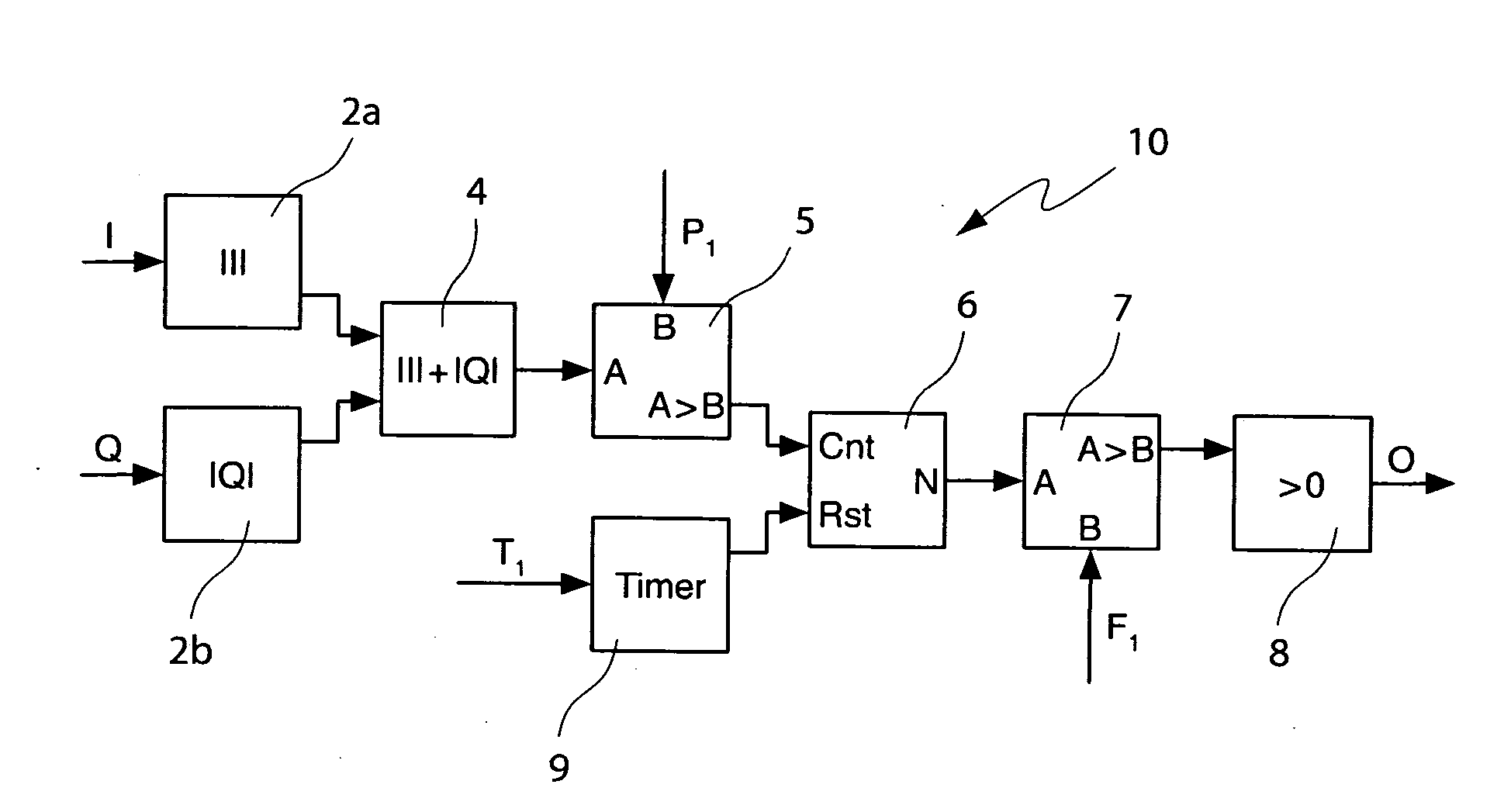
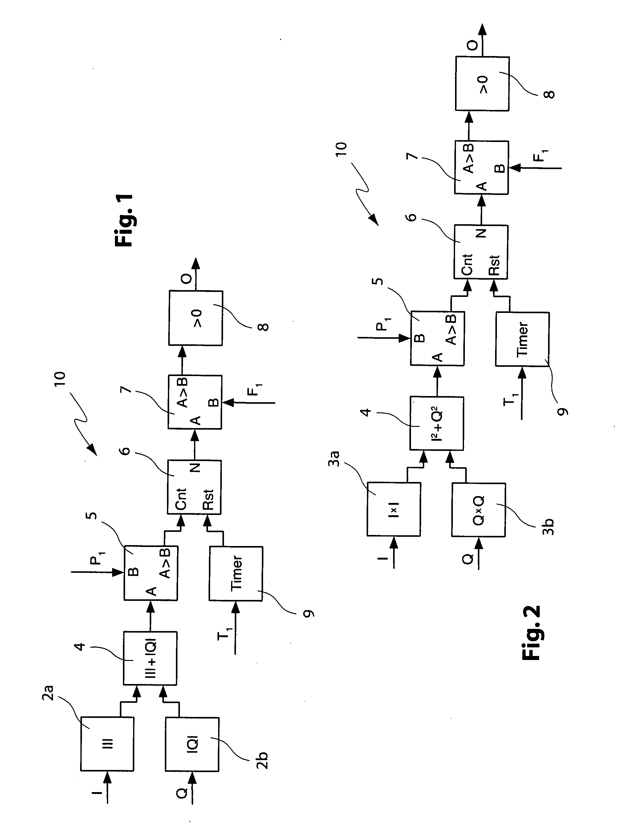
[0063]FIG. 1 illustrates the present invention, a device 10 for use in a COFDM communication application, where the 1-component and the Q-component of the signal are fed to second and third mixer units 2a, 2b, respectively. The second and third mixer units are operative to provide as a signal output the magnitude of the input signal, i.e., the second mixer outputs the magnitude of the I-component of the COFDM signal and the third mixer outputs the magnitude of the Q-components of the COFDM signal.

[0064] The outputs of the second and third mixers are fed to the first mixer 4, which performs an additive mix such that the magnitudes of the I-component and the Q-component of the COFDM signal are added, thus providing a sufficiently accurate estimate of the instantaneous signal level of the COFDM signal.

[0065] This value represents the first signal, which is fed to a first input A of a first comparator 5. The first comparator 5 is also fed a first level threshold value P1 at a second in...

third embodiment

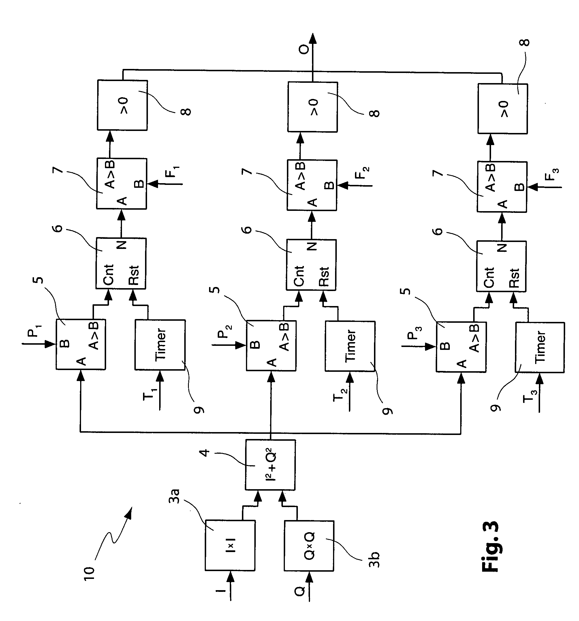
[0072]FIG. 3 shows the present invention in which a multistage analysis of the information signal is performed. The structure of every single state of the device 10 according to FIG. 3 resembles the structure of the device according to FIG. 2, whereby the first signal being an output of the first mixer 4 is fed to first inputs A of the first comparators 5 of every single state, respectively. Correspondingly, every single stage of device 10 according to FIG. 3 is also fed a first, second and third level threshold value P1, P2, P3, respectively, at second inputs B of the first comparators 5.

[0073] Timers 9 of each stage are fed first, second and third predetermined time interval values T1, T2, T3, resulting in the counters 6 being periodically reset after respective time units, respectively. The second comparators 7 are, correspondingly, fed with first, second and third frequency threshold values F1, F2, F3. The output signals of every one of the three stages of the device 10 accordin...


PUM


Abstract

A method for detecting a-condition, where the signal level of an information signal, particularly of an orthogonal frequency division multiplexed (OFDM) digital information signal, exceeds at least one upper predetermined signal level and/or underruns at least one lower predetermined signal level for at least a predetermined time interval by feeding the information signal to at least one first mixer unit for producing a first signal and comparing said first signal to a at least a first level threshold value. Counting the number of incidences per time unit where said first signal is above or below said first level threshold value and comparing said number of incidences per time unit to a first frequency threshold value allows determination, if the condition is met or not. A device for detecting a condition, where the signal level of an information signal, particularly of an orthogonal frequency division multiplexed (OFDM) digital information signal, exceeds at least one upper predetermined signal level and/or underruns at least one lower predetermined signal level for at least a first predetermined time interval comprises at least one first mixer unit to which the information signal is fed for producing an output of a first signal, which is fed to at least one first comparator for comparing the first signal to a first level threshold value. Feeding the output of the first comparator to at least one counter for counting the number of incidences per time unit and comparing the output of the counter indicating the number of incidences per time unit to a first frequency threshold value using at least one second comparator allows determination, if the condition is met or not.

Description

RELATED APPLICATIONS [0001] This application claims the benefit of European Patent Application No. 06 110 997.1, filed Mar. 10, 2006 and U.S. Provisional Patent Application, Ser. No. 60 / 781,319, filed Mar. 13, 2006.BACKGROUND OF THE INVENTION [0002] The present invention refers to a method and a device for detecting an amplitude level of an information exceeding or underrunning predetermined threshold amplitude levels. Particularly, the present invention refers to a method and a device for detecting a condition, where the signal level of an information signal, particularly of a digital information signal, exceeds at least one upper predetermined signal level and / or underruns at least one lower predetermined signal level for at least a first predetermined time interval. DESCRIPTION OF THE PRIOR ART [0003] Information signals, particularly digital information signals, are ubiquitous in various aspects of communication technologies. Particularly, in digital communication technologies s...

Claims


Application Information

Patent Timeline
Patent Type & Authority Applications(United States)
IPC IPC(8): H04J11/00
CPCH04L27/2614
Inventor SCHOENBECK, DIETMAR
Owner HARRIS CORP
Why Eureka
Try Eureka