
Improved flushing structure of closestool

A flushing and toilet technology, applied in the field of sanitary ware, can solve the problems of poor compatibility of toilets, pollution of domestic water sources, poor connectivity with tap water pipelines, etc., and achieve the effects of reasonable design, convenient flushing operation, and prevention of siphons

Inactive Publication Date: 2018-04-10
宁波泰芸电气有限公司
View PDF0 Cites 0 Cited by
  • Summary
  • Abstract
  • Description
  • Claims
  • Application Information

AI Technical Summary

Problems solved by technology

[0002] With the development of my country's economy and the improvement of residents' living environment, the sanitary ware in the indoor toilet is also gradually improving. The toilet is generally indispensable in the bathroom. The toilet flushing water and drinking water used in daily life come from the same tap water pipe, and the toilet tank The water inlet valve of the toilet is connected to the tap water supply pipe. When the water pipe is cut off, the pipe will form a negative pressure, and the water inlet valve of the toilet tank connected to the main pipe will produce a siphon phenomenon. Once the dirt cannot be discharged during use, Even when the dirt is poured back, the dirt in the toilet will reach the position of the seat surface. If there is no tap water, the siphon phenomenon will appear in the tap water pipe, which will pollute the domestic water source. Therefore, the existing toilet water tank is generally equipped with an anti-siphon structure , however, the water inlet pipe at the bottom of the existing toilet has poor connectivity with the tap water pipe, resulting in poor compatibility of the toilet and unable to effectively prevent the occurrence of siphons

Method used


Image

  • Improved flushing structure of closestool
  • Improved flushing structure of closestool

Examples


Embodiment

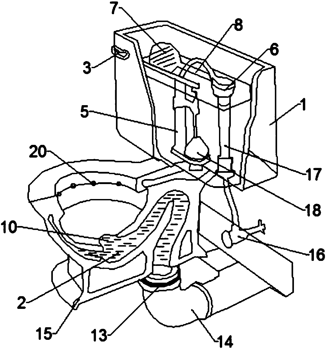
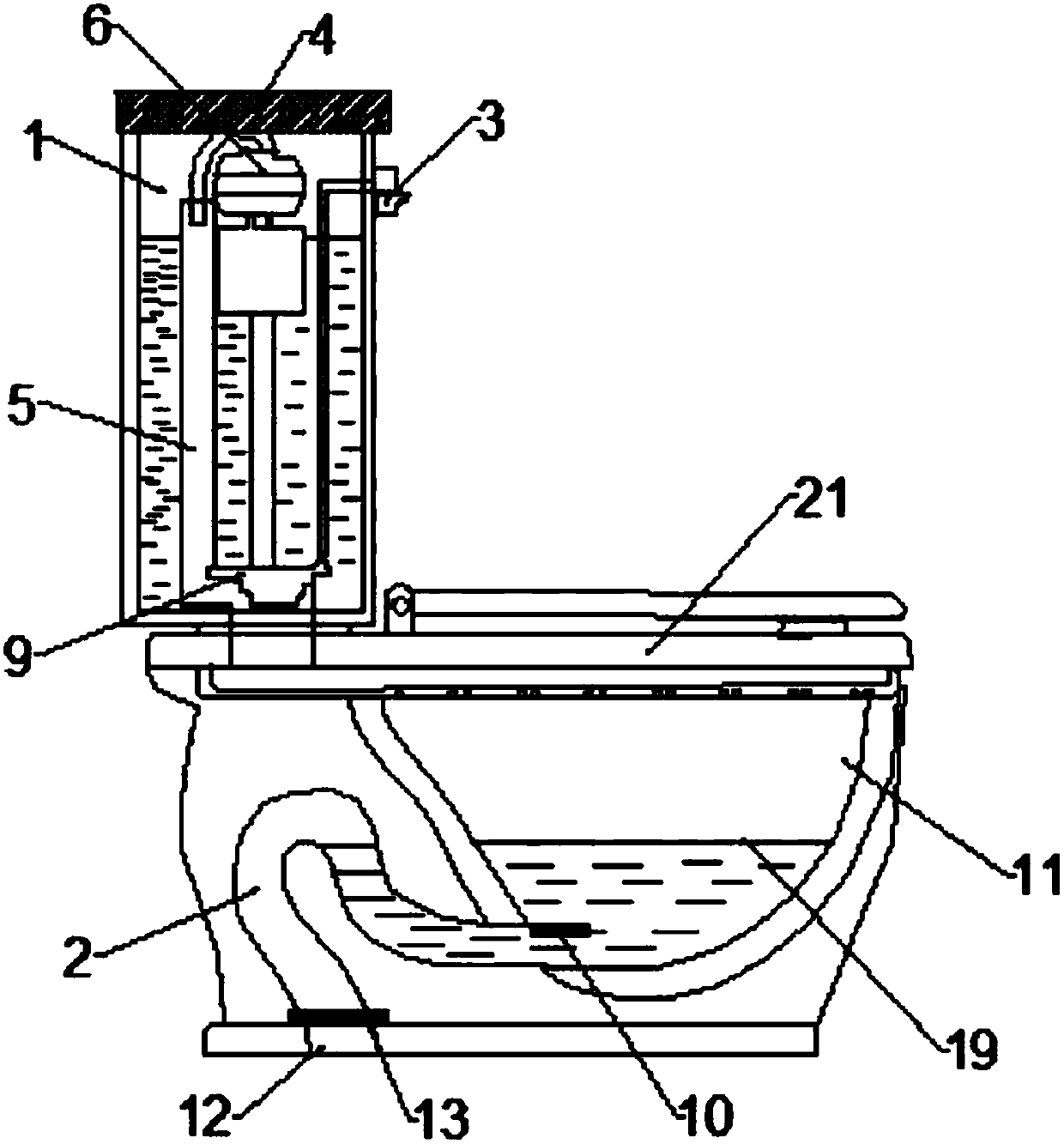
[0018] see figure 1 and figure 2 , the present invention provides a technical solution: an improved toilet flushing structure, including a water tank 1 and a siphon 2, a flushing handle 3 and a cover plate 4 are fixedly installed on the outer surface of the water tank 1, and the cover plate 4 is arranged on the water tank 3 On the upper surface of the water tank 1, an overflow pipe 5 is fixedly installed inside the water tank 1, and a water inlet pipe 17 is fixedly installed on the right side of the overflow pipe 5, and an angle valve 16 is also fixedly installed at the bottom of the water tank 1, and the top of the overflow pipe 5 An injection valve 6 and a floating ball 7 are fixedly installed, and the floating ball 7 is fixedly installed on the left side of the injection valve 6 through an air guide pipe 8 installed on its top, and a flush valve 9 is arranged at the bottom end of the overflow pipe 5, and the overflow Also be provided with water-stop rubber ring 18 between...


PUM


Abstract

The invention discloses an improved toilet flushing structure, which comprises a water tank and a siphon pipe, a flushing handle and a cover plate are fixedly installed on the outer surface of the water tank, an overflow pipe is fixedly installed inside the water tank, and the top end of the overflow pipe is fixedly installed There is an injection valve and a floating ball, the floating ball is fixedly installed on the left side of the injection valve through the air guide pipe installed on the top, a flush valve is installed at the bottom of the overflow pipe, and an angle valve is also fixedly installed at the bottom of the water tank; The top of the siphon tube is fixedly equipped with a water inlet and a barrel body, and the barrel body is fixedly connected with the siphon tube through the water inlet installed at the bottom end of the siphon tube. , The outer surface of the siphon tube is fixedly installed with a base. The improved toilet flushing structure has simple design, reasonable structure, convenient installation and maintenance, effectively improves the anti-siphon effect, and achieves the purpose of safety and cleanliness.

Description

technical field [0001] The invention relates to the technical field of sanitary ware, in particular to an improved toilet flushing structure. Background technique [0002] With the development of my country's economy and the improvement of residents' living environment, the sanitary ware in the indoor toilet is also gradually improving. The toilet is generally indispensable in the bathroom. The toilet flushing water and drinking water used in daily life come from the same tap water pipe, and the toilet tank The water inlet valve of the toilet is connected to the tap water supply pipe. When the water pipe is cut off, the pipe will form a negative pressure, and the water inlet valve of the toilet tank connected to the main pipe will produce a siphon phenomenon. Once the dirt cannot be discharged during use, Even when the dirt is poured back, the dirt in the toilet will reach the position of the seat surface. If there is no tap water, the siphon phenomenon will appear in the tap ...

Claims


Application Information

Patent Timeline
Patent Type & Authority Applications(China)
IPC IPC(8): E03D1/32E03D1/33E03D1/34E03D9/08E03D11/18E03D11/17
CPCE03D1/32E03D1/33E03D1/34E03D9/08E03D11/17E03D11/18
Inventor 陈杰
Owner 宁波泰芸电气有限公司
Learn More