Fixing device for grinding equipment
A technology of fixing devices and equipment, which is applied in the direction of grinding workpiece supports, etc., can solve the problems of low grinding efficiency, loose castings, inconvenient operation of grinding parts, etc., and achieve good stability
- Summary
- Abstract
- Description
- Claims
- Application Information
AI Technical Summary
Problems solved by technology
Method used
Image

Examples
Embodiment Construction
[0019] In order to make the technical means, creative features, goals and effects achieved by the present invention easy to understand, the present invention will be further elaborated below in conjunction with illustrations and specific embodiments.
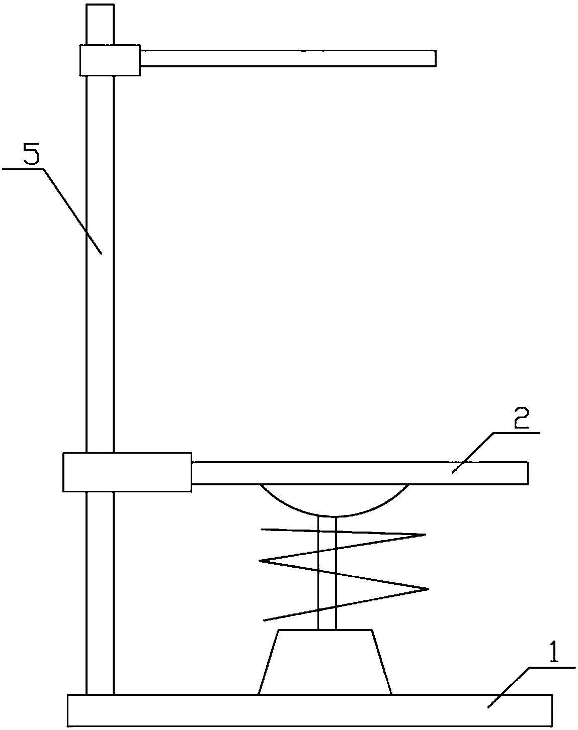
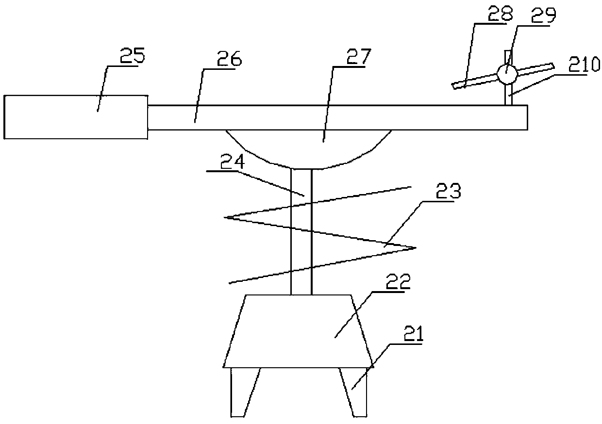
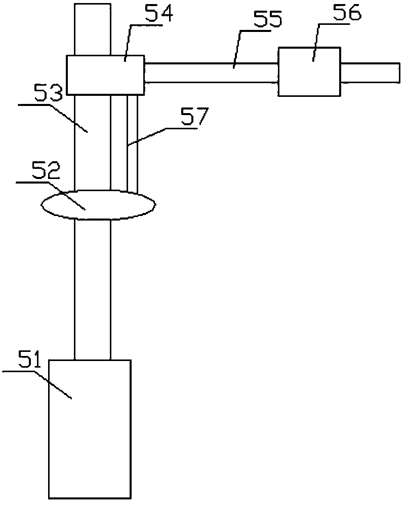
[0020] combine Figure 1 to Figure 3 The fixing device for grinding equipment of the present invention will be described in detail.
[0021] A fixing device for grinding equipment, comprising a base plate 1, a carrier frame 2 clamped on the upper end of the base plate 1, and a frame 5 clamped on the edge of the upper end of the base plate 1;
[0022] The frame 5 includes an elevating tube 51, a main mounting rod 53 passing through the upper part of the elevating tube 51 along the axial direction of the elevating tube 51, and a main mounting rod 53 screwed to the middle part of the main mounting rod 53 by threads. The first fixing part 52, the second fixing part 54 screwed on the upper part of the main mounting rod 53 through th...
PUM
 Abstract
Description
Claims
Application Information
PatSnap Eureka turns technology decisions into work you can execute. Powered by our Innovation Knowledge Graph, it runs expert workflows across engineering, life sciences, materials and intellectual property. Get your review-ready output in minutes.


