
Liquid crystal display panel and liquid crystal display device

A liquid crystal display panel and liquid crystal layer technology, which is applied in the directions of instruments, nonlinear optics, optics, etc., can solve the problems of sawtooth, edge chromatic aberration of special-shaped liquid crystal display devices, etc., to achieve uniform display, solve color unevenness, and improve visual effects.

Active Publication Date: 2020-10-30
KUSN INFOVISION OPTOELECTRONICS
View PDF16 Cites 0 Cited by
  • Summary
  • Abstract
  • Description
  • Claims
  • Application Information

AI Technical Summary

Problems solved by technology

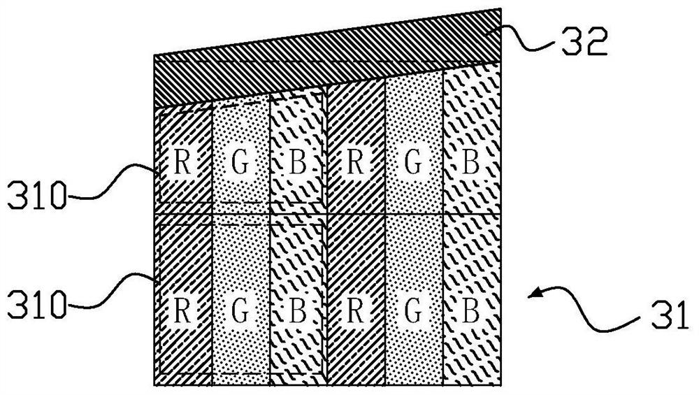
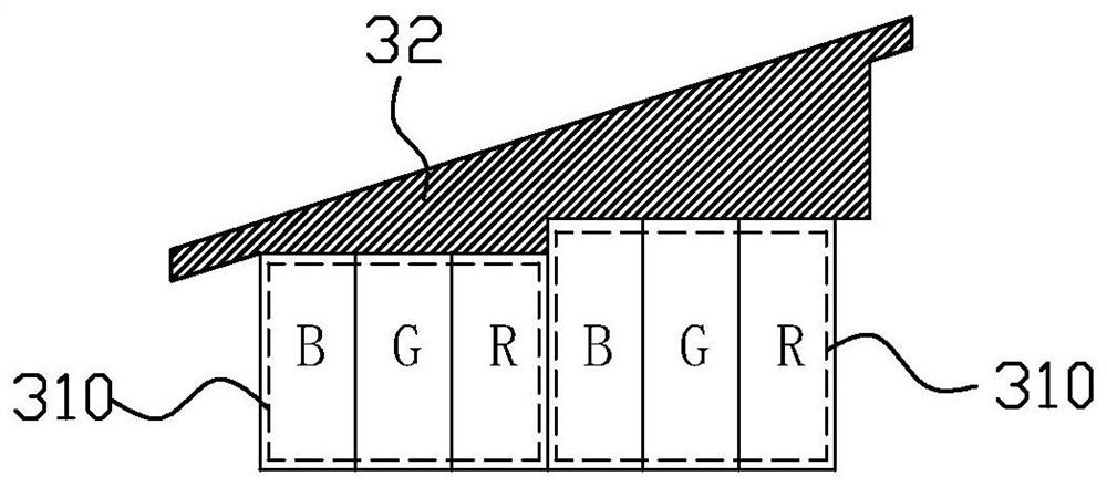
[0006] The purpose of the present invention is to provide a liquid crystal display panel to solve the problem of color difference and sawtooth on the edge of the existing special-shaped liquid crystal display device

Method used


Image

  • Liquid crystal display panel and liquid crystal display device
  • Liquid crystal display panel and liquid crystal display device
  • Liquid crystal display panel and liquid crystal display device

Examples


Embodiment Construction

[0025] In order to further explain the technical means and effects of the present invention to achieve the intended purpose of the invention, the specific implementation, structure, features and effects of the present invention will be described in detail below in conjunction with the accompanying drawings and examples.

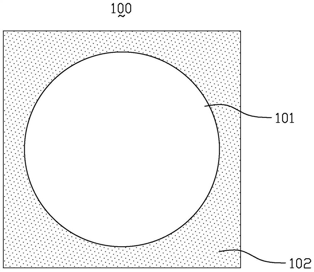
[0026] image 3 is a schematic plan view of the liquid crystal display panel in the first embodiment of the present invention, Figure 4 It is a schematic plan view of the planar structure on the second substrate in the first embodiment of the present invention, Figure 5 for image 3 A cutaway view of the middle display area away from the display edge. Please combine Figure 3 to Figure 5 , the liquid crystal display panel 100 provided by the present invention includes a first substrate 10 , a second substrate 20 and a liquid crystal layer 30 disposed between the first substrate 10 and the second substrate 20 .

[0027] The liquid crystal display panel 1...


PUM


Abstract

The invention relates to a liquid crystal display panel. The liquid crystal display panel includes a first substrate, a second substrate and a liquid crystal layer. The liquid crystal display panel isprovided with a display area and a non-display area. The non-display area includes a black matrix. The second substrate is provided with common electrodes which are insulated from each other and a plurality of pixel electrodes. The display area of the liquid crystal display panel includes a plurality of first pixel units near the edge of the display area, and each first pixel unit includes a plurality of first sub-pixels. At least one hollow portion is disposed on the common electrode corresponding to the first sub-pixel which has a larger pixel area in the first sub-pixels, so that light transmittance of each first sub-pixel in the respective first pixel unit is equal. In the liquid crystal display panel, by arranging the hollow portion on the common electrode corresponding to each firstpixel unit, the electric field intensity of liquid crystal in the sub-pixels in each first pixel unit is equal, that is, the light transmittance of each first sub-pixel is equal, so that the displaypanel edge color is displayed evenly.

Description

technical field [0001] The invention relates to the technical field of liquid crystal display, in particular to a liquid crystal display panel and a liquid crystal display device. Background technique [0002] With the development of science and technology, people's demand for screen display is more and more diversified. People no longer only meet the conventional performance indicators such as large size and high definition of the display panel, but have higher requirements for the appearance of the display panel. . [0003] At present, the emergence of special-shaped display panels not only makes the display effect more diversified, but also improves the limitation of the single rectangular structure of the display panel. The application of shaped display panels has become more and more widespread, and has been successfully applied to wearable electronic devices such as watches, glasses or smart bracelets. The special-shaped display panel usually has a special-shaped dis...

Claims


Application Information

Patent Timeline
Patent Type & Authority Patents(China)
IPC IPC(8): G02F1/1343G02F1/1335
CPCG02F1/133512G02F1/134309G02F2201/121G02F2201/123
Inventor 黄清英蒋隽房耸李红侠
Owner KUSN INFOVISION OPTOELECTRONICS
Learn More