Disparity map-based road detection method and device

A road detection and disparity map technology, which is applied in the field of image processing, can solve the problems of mistakenly deleted obstacle parallax, inaccurate obstacle detection results, and inability to delete distant road parallax, etc., to achieve the effect of improving accuracy

Active Publication Date: 2018-04-13
HISENSE
View PDF2 Cites 6 Cited by
  • Summary
  • Abstract
  • Description
  • Claims
  • Application Information

AI Technical Summary

Problems solved by technology

[0003] However, the above method of deleting the road surface is only suitable for ideally flat roads, and the roads in actual scenarios are likely to be undulating, such as from flat roads to downhill roads, from uphill roads to flat roads, and even other more complex roads. For this type of road conditions, it is difficult to use a straight line for fitting because the transition zone of different road sections usually manifests as a circular arc transition. Therefore, if a Hough straight line is used to detect the parallax point of the road surface, it is easy to cause The obstacle parallax is deleted by mistake in the road section, or the distant road surface parallax cannot be deleted, resulting in inaccurate obstacle detection results in the later stage
[0004] Based on this, it is proposed in the prior art to segment the road according to the distance and the undulations of the road surf

Method used


Image

  • Disparity map-based road detection method and device
  • Disparity map-based road detection method and device
  • Disparity map-based road detection method and device

Examples


Embodiment 1

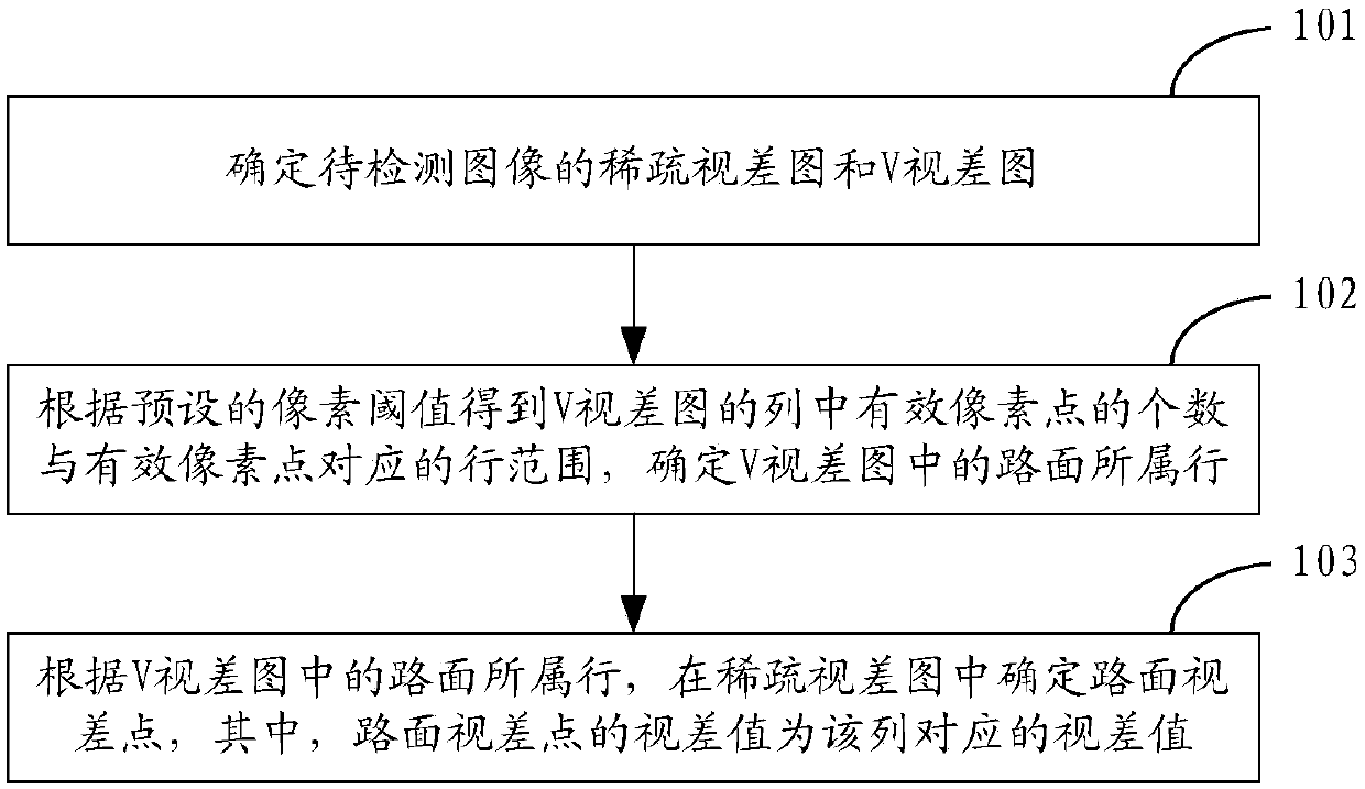
[0040] See Figure 1A , is a flowchart of an embodiment of the road detection method based on the disparity map of the present application, the method includes the following steps:

[0041] Step 101: Determine the sparse disparity map and V disparity map of the image to be detected.

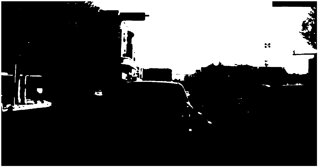
[0042] In the embodiment of the present application, for the convenience of description, the two original images collected by the binocular camera can be referred to as images to be detected, such as Figure 1B Shown is an example of the grayscale image of the image to be detected.

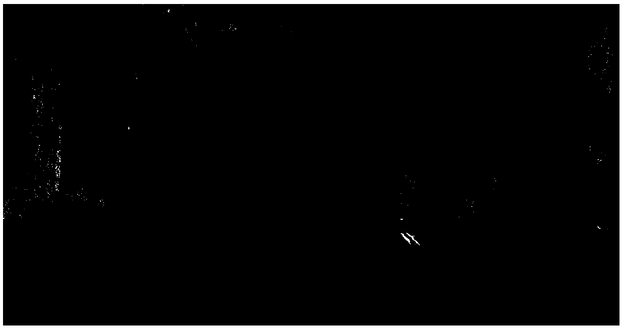
[0043] In related technologies, stereo matching algorithms can be classified according to different primitives used, one of which is feature-based stereo matching algorithms. In the feature-based stereo matching algorithm, the disparity estimation is mainly based on geometric feature information, such as edges, contours, points of interest, lines, corners, etc. Therefore, in the disparity map obtained by the feature...

Embodiment 2

[0051] See figure 2 , which is a flow chart of another embodiment of the road detection method based on the disparity map of the present application, figure 2 The illustrated method focuses on the above step 102 and step 103, that is, the process of determining the road parallax point in the sparse disparity map by processing the V disparity map. The method may include the following steps:

[0052] Step 201: For each column in the V-disparity map, obtain the number of effective pixels in the column and the row range corresponding to the effective pixels according to the preset pixel threshold.

[0053] In the embodiment of the present application, taking one column of the V disparity map as an example, the pixels in the column can be detected line by line from top to bottom, and the pixel value of the detected pixel point can be compared with the preset pixel threshold value. If the pixel value of the detected pixel is greater than the preset pixel threshold, the detected p...

Embodiment 3

[0079] See image 3 , is a flow chart of another embodiment of the road detection method based on the disparity map of the present application, the image 3 The illustrated embodiment focuses on how to determine the row search range in the column, which may include the following steps:

[0080] Step 301: Multiply the preset truncation ratio by the number of effective pixels in the column to obtain the number S of effective parallax.

[0081] In this step, the number S of effective parallaxes can be calculated according to the following formula (3).

[0082] S=A[0][0]*R Formula (3)

[0083] In the above formula (3), R is a preset truncation ratio.

[0084] Those skilled in the art can understand that the above-mentioned number of effective parallaxes S should be an integer. If S calculated by the formula (3) is not an integer, the calculation result can be further "rounded" to obtain the number of effective parallaxes number S.

[0085] Step 302 : In the column, start from...


PUM


Abstract

The invention provides a disparity map-based road detection method and device, and relates to the technical field of image processing. The method comprises the following steps of: determining a sparsedisparity map and a V disparity map of a to-be-detected image; obtaining the number of effective pixel points in a column of the V disparity map and a row range corresponding to the effective pixel points according to a preset pixel threshold value, and determining a row to which a road surface in the V disparity map belongs; and determining a road surface parallax point in the sparse disparity map according to the row to which the road surface in the V disparity map belongs, wherein a parallax value of the road surface parallax point is a parallax value corresponding to the column. By applying the method, the correctness and efficiency for determining road surface parallax points in disparity map images can be improved; and the method is suitable for scenes with undulating practical roadsurfaces.

Description

technical field [0001] The present application relates to the technical field of image processing, and in particular, to a method and device for road detection based on a disparity map. Background technique [0002] In recent years, the obstacle detection method based on Binocular Stereo Vision technology has become a research hotspot in the field of assisted driving. Before detecting obstacles based on parallax images, road parallax points are accurately detected and the road parallax points are deleted. It is especially important for obstacle detection results. In the prior art, a sparse disparity map is first generated based on the road image collected by the binocular camera, then a V disparity map is generated based on the sparse disparity map, and one or more straight lines are detected in the V disparity map by using the Hough line detection method. To fit the straight line equation of the road surface in the V disparity map, then, find the disparity points that sati...

Claims


Application Information

Patent Timeline
IPC IPC(8): G06K9/00
CPCG06V20/588G06V20/58
Inventor 冯谨强
Owner HISENSE
Why Eureka
Try Eureka