
Laparoscopic 3D monitoring equipment with multiple focal depths and multiple spectral segments

A technology of monitoring equipment and laparoscopy, which is applied in the field of medical imaging, can solve problems such as prolonged operation time, no sense of distance in the screen, and potential safety hazards, and achieve the effects of ensuring surgical safety, reducing the difficulty of surgical operations, and improving safety

Inactive Publication Date: 2016-11-23
SUN YAT SEN UNIV
View PDF8 Cites 0 Cited by
  • Summary
  • Abstract
  • Description
  • Claims
  • Application Information

AI Technical Summary

Problems solved by technology

The main problem of this kind of single-lens laparoscopy is that the projected picture has no sense of distance, and the three-dimensional depth cannot be seen, which brings great difficulties to the operation.
Doctors need to use a lot of experience to infer the three-dimensional relationship between the adjacent structure of blood vessels in the lesion and the direction of the tissue. This will not only prolong the operation time, but also easily injure healthy tissues by accident, bringing serious safety hazards and increasing the chance of complications and mortality

Method used


Image

  • Laparoscopic 3D monitoring equipment with multiple focal depths and multiple spectral segments
  • Laparoscopic 3D monitoring equipment with multiple focal depths and multiple spectral segments
  • Laparoscopic 3D monitoring equipment with multiple focal depths and multiple spectral segments

Examples


Embodiment 1

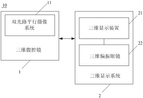
[0046] see figure 1, is a structural block diagram of a laparoscopic three-dimensional monitoring device with multiple focal depths and multiple spectral segments provided by an embodiment of the present invention. The multi-focus, multi-spectral laparoscopic three-dimensional monitoring equipment 10 includes a three-dimensional laparoscope 1 with a dual optical path parallel camera system 11 and a three-dimensional display system 2. The three-dimensional display system 2 includes a three-dimensional display device 21 and a three-dimensional Polarized glasses22. The three-dimensional laparoscope 1 is a double-lens laparoscope that can be inserted into the body through an organ tube to capture multi-focal surgical images in the patient's abdominal cavity and convert them into 3D stereoscopic images for display by the three-dimensional display device 21, while the user ( For example, a patient) can observe a 3D surgical field of view on the 3D display device 21 after wearing th...

Embodiment 2

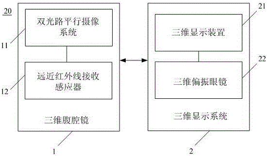
[0055] Such as image 3 Shown is a structural block diagram of a laparoscopic three-dimensional monitoring device with multiple focal depths and multiple spectral segments provided by the second embodiment of the present invention. Like Embodiment 1, the laparoscopic three-dimensional monitoring system 20 provided in this embodiment includes a three-dimensional laparoscope 1 with a dual optical path parallel camera system 11 and a three-dimensional display system 2, and the three-dimensional display system 2 includes a three-dimensional display device 21 used in conjunction with each other And three-dimensional polarizing glasses 22. The three-dimensional laparoscope 1 is a double-lens laparoscope that can be inserted into the body through an organ tube, so as to capture multi-focal surgical images in the patient's abdominal cavity and convert them into 3D stereoscopic image displays through the three-dimensional display device 21. After wearing the three-dimensional polarizi...

Embodiment 3

[0063] refer to Figure 4 , is a structural block diagram of a laparoscopic three-dimensional monitoring device with multiple focal depths and multiple spectral segments provided by the third embodiment of the present invention. Like Embodiment 2, the laparoscopic three-dimensional monitoring system 30 provided in this embodiment includes a three-dimensional laparoscope 1 and a three-dimensional display system 2 with a dual optical path parallel camera system 11 and a far-near infrared receiving sensor 12, and the three-dimensional display system 2 includes mutual A three-dimensional display device 21 and three-dimensional polarizing glasses 22 are used in conjunction. The three-dimensional laparoscope 1 is a double-lens laparoscope that can be inserted into the body through an organ tube, so as to capture multi-focal surgical images in the patient's abdominal cavity and convert them into 3D stereoscopic image displays through the three-dimensional display device 21. After we...


PUM


Abstract

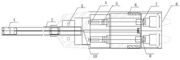
The invention discloses multi-focal-depth and multi-spectrum-section laparoscope three-dimensional monitoring equipment which comprises a three-dimensional laparoscope with a double-light-path parallel image pickup system, and the three-dimensional display system. The three-dimensional display system comprises a three-dimensional display device and three-dimensional polarization glasses. The three-dimensional laparoscope comprises a laparoscope shell and a double-light-path image pickup system disposed in the laparoscope shell. A multi-spectrum transmitting source and a lens are disposed between the two light paths of the double-light-path image pickup system. Light waves transmitted by the multi-spectrum transmitting source passes the lens to form parallel light, and the parallel light is combined with the double-light-path image pickup system to form the double-light-path parallel image pickup system. A light transmitting bundle socket is further disposed inside the laparoscope shell and used for being connected with an external image collecting and processing system to alternately display the left-eye surgery images and the right-eye surgery images, picked up by the double-light-path parallel image pickup system, in the three-dimensional display device.

Description

technical field [0001] The invention relates to the field of medical imaging, in particular to a laparoscopic three-dimensional monitoring device with multiple focal depths and multiple spectral segments. Background technique [0002] Currently, the in vivo observation instrument used in the medical field is usually a two-dimensional laparoscope. This two-dimensional laparoscope is a single-lens laparoscope that can be inserted into the body through the organ tube. This single-lens laparoscope is composed of a puncture tube, an optical fiber puncture rod arranged in it, and a camera lens installed at the insertion end of the optical fiber. After the optical fiber puncture rod is connected to the corresponding monitor, the picture taken by the camera when the optical fiber puncture rod is inserted can be observed through the monitor. The main problem of this single-lens laparoscope is that the projected picture has no sense of distance and cannot see the three-dimensional d...

Claims


Application Information

Patent Timeline
Patent Type & Authority Patents(China)
IPC IPC(8): A61B1/313A61B1/05A61B5/0205
CPCA61B1/00045A61B1/00131A61B1/05A61B1/313A61B5/0075A61B5/02055
Inventor 顾怀宇邱帅王晖
Owner SUN YAT SEN UNIV
Learn More