Wire positioning device of insulator

A technology for positioning devices and insulators, which is applied in the direction of insulators, electrical components, circuits, etc., can solve the problems of wire casualties, wire wear, and broken wires, and achieve the effects of avoiding fixed binding methods, reducing wear rates, and improving safety

Inactive Publication Date: 2018-04-13
STATE GRID SHANDONG ELECTRIC POWER COMPANY WEIFANG POWER SUPPLY +1
View PDF6 Cites 2 Cited by
  • Summary
  • Abstract
  • Description
  • Claims
  • Application Information

AI Technical Summary

Problems solved by technology

The wire on the traditional 10 kV distribution line is fixed by binding the steel core aluminum wire (overhead insulated wire) to the porcelain insulator with an aluminum wire (sheath wire). This method has been used in China and has not changed until now. In practice, we found that it has the following defects: (1) Due to the natural monsoon, rain, and snow force between the wire and the bound wire and the insulator, there is a slight vibration between the wire and the bound wire and the insulator
Under the action of external force for a long time, the binding wire will gradually loosen, resulting in complete loosening of the binding wire, wear of the wire, wear of the porcelain insulator, and even the wire is simply worn off in the end, resulting in power failure and personal injury accidents caused by the wire falling
(2) Although there are requirements for binding methods in the binding operation using aluminum binding wires, because each person's method is different or the same person cannot be consistent every time, the quality of binding is greatly affected by human factors, and the level of construction technology is difficult. control
(3) After the construction is completed, it is difficult to control and find out the construction process due to the difficulty in acceptance at high altitudes.
(4) Due to the huge number of insulators on the 10 kV distribution line, regular maintenance is difficult

Method used


Image

  • Wire positioning device of insulator
  • Wire positioning device of insulator
  • Wire positioning device of insulator

Examples


Embodiment Construction

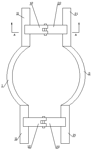
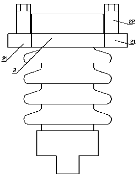
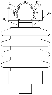
[0016] Such as figure 1 The shown insulator wire positioning device includes a first semicircular clamp 1 installed between the upper cap of the insulator and the ceramic part of the insulator and a second semicircular clamp 2 opposite to the first semicircular clamp 1 , both ends of the first semicircular clamp 1 are provided with a relatively outwardly extending first extension section 11, and both ends of the second semicircular clamp 2 are provided with a relatively outwardly extending section 11 that is in line with the first extension section. 11 parallel to the second extension section 21 , a locking device is provided between the end of the first extension section 11 and the end of the second extension section 21 . In this embodiment, the locking device includes a bolt arranged between the end of the first extension section 11 and the end of the second extension section 21, and the extended end of the bolt is provided with a lock nut, which can be locked by turning the...


PUM


Abstract

The invention discloses a wire positioning device of an insulator. The wire is placed in the groove arranged on the upper surface of the insulator upper cap; the wire passes through circular cavitiesarranged at the two ends of the groove; a first half round clamp and a second half round clamp are clamped between the insulator upper cap and the insulator porcelain piece by locking the locking nutarranged on the locking device; and meanwhile, a first arc clamping section and a second arc clamping section at both ends clamp the wire harness in the circular cavity for positioning. When the wireharness is small, a first arc adjustment section and a second arc adjustment section are used for micro-adjustment, that is, the position of each arc adjustment section is adjusted by screwing the locking nut arranged at the end of each adjusting rod to clamp the wire harness for positioning. By means of the wire positioning device of the insulator, the fixing with binding mode is avoided, and thesecurity of wire positioning is improved.

Description

technical field [0001] The invention relates to an insulator wire positioning device. Background technique [0002] With the rapid development of my country's national economy and the rapid improvement of people's living standards, the demand for electricity is increasing, and higher requirements are put forward for the reliability, quality and safety of power supply. The normal operation of 10kV distribution lines is directly related to people's work, study and life, so it is very important to ensure the safe, stable and trouble-free operation of the 10kV overhead line distribution network system. The existing insulator comprises an insulating porcelain part, an upper cap and a lower cap installed at both ends of the insulating porcelain part, and the upper cap is provided with grooves for placing wires. The wire on the traditional 10 kV distribution line is fixed by binding the steel core aluminum wire (overhead insulated wire) to the porcelain insulator with an aluminum ...

Claims


Application Information

Patent Timeline
Patent Type & Authority Applications(China)
IPC IPC(8): H01B17/24H01B17/38
CPCH01B17/24H01B17/38
Inventor 辛洪杰孙华忠邵明波乔丕凡辛庚鑫张兆慧张凯李金宝徐鹏刘炳仁李国强毕盛伟于金亮高兴琳尹磊段磊刘五超王杰马献辉于欣杨栋张金良吴冰刘其博王路
Owner STATE GRID SHANDONG ELECTRIC POWER COMPANY WEIFANG POWER SUPPLY
Why Eureka
Try Eureka