Magnetizing device and magnetizing method for six-sided magnetic suspension body

A magnetizing device and magnetic levitation technology, which are applied to magnetic objects, electrical components, circuits, etc., can solve the problem of inability to realize the magnetization of a six-sided magnetic levitation body, achieve a simple and practical method of magnetization, improve magnetization efficiency, and improve mechanical properties. The effect of automation

Active Publication Date: 2018-04-13
徐州新南湖科技有限公司
View PDF2 Cites 2 Cited by
  • Summary
  • Abstract
  • Description
  • Claims
  • Application Information

AI Technical Summary

Problems solved by technology

[0004] Regarding the six-sided magnetic levitation body, the structure of each surface includes an outer layer of permanent magnetic material and an inner core of soft magnetic material. magnetizing head), it is impossible to magnetize the six-sided magnetic levitation body

Method used


Image

  • Magnetizing device and magnetizing method for six-sided magnetic suspension body
  • Magnetizing device and magnetizing method for six-sided magnetic suspension body
  • Magnetizing device and magnetizing method for six-sided magnetic suspension body

Examples


Embodiment 1

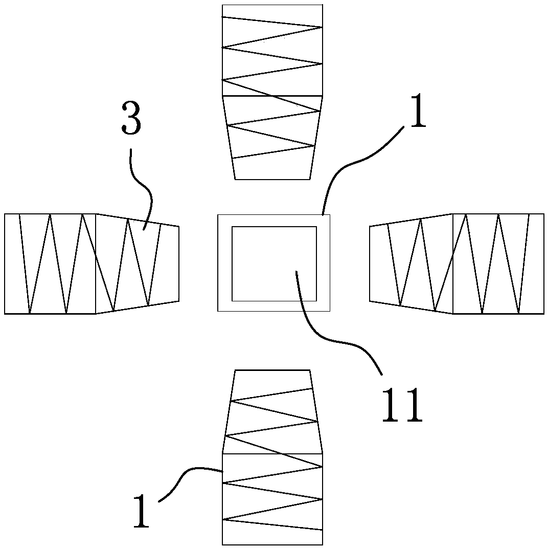
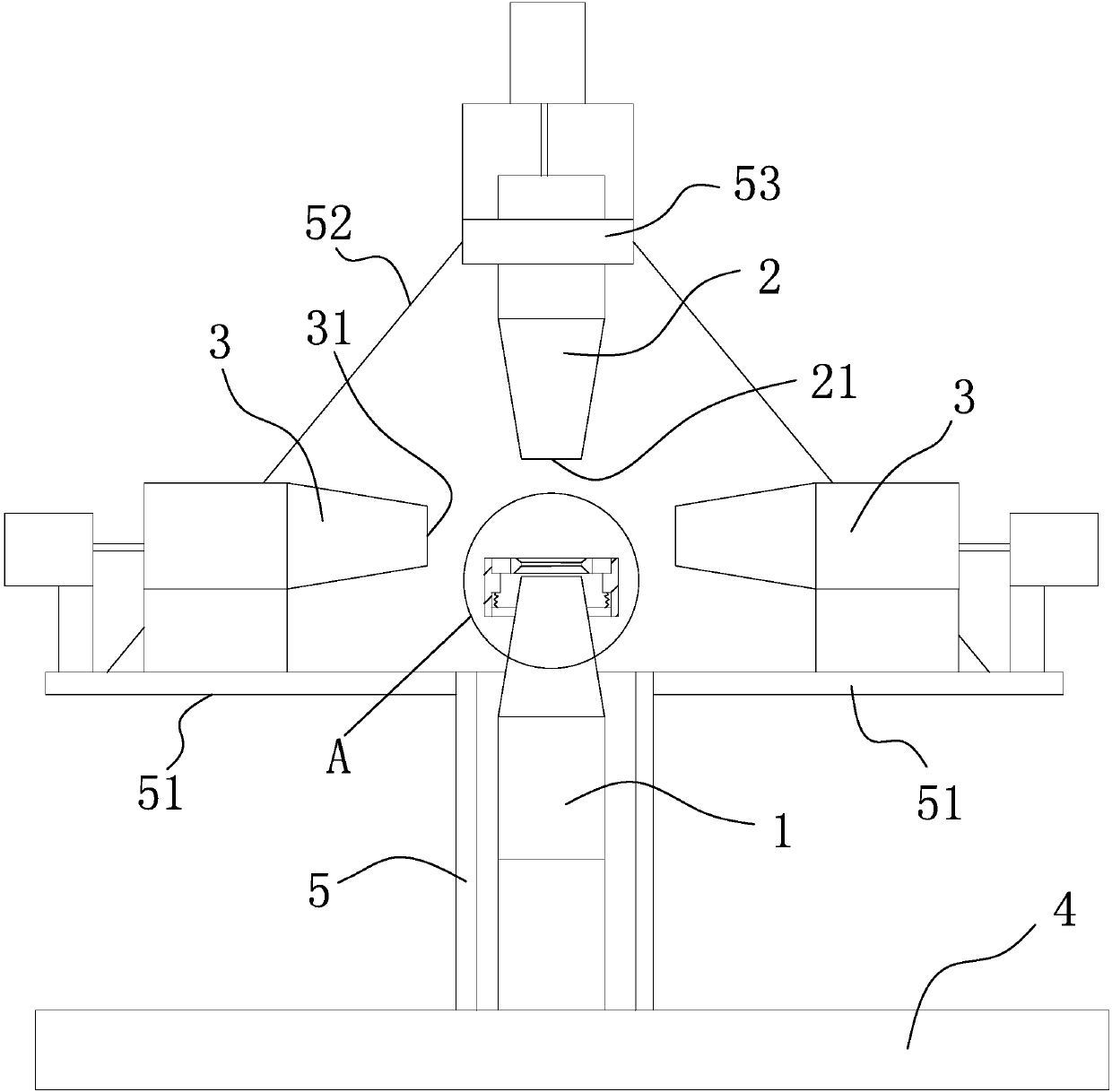
[0051] Such as figure 1 As shown, the magnetizing device of the six-sided magnetic levitation body includes a vertically arranged lower magnetizing head 1 and an upper magnetizing head 2 directly above the lower magnetizing head 1, and the device also includes four circumferentially distributed and horizontally arranged side faces Charging head 3,

[0052] The above-mentioned lower magnetic charging head 1 , upper magnetic charging head 2 and side surface magnetic charging head 3 are respectively arranged on the frame.

[0053] Such as image 3 As shown, further, the lower charging head 1 is fixed on the frame 4 .

[0054] The frame 4 is provided with a second lift drive mechanism that drives the upper magnetic charging head 2 to move up and down in the vertical direction.

[0055]Each side magnetic charging head 3 is respectively connected with a horizontal driving mechanism, and said horizontal driving mechanism is respectively connected on the frame 4 .

[0056] The lat...

Embodiment 2

[0073] The structure and principle of this embodiment are basically the same as that of Embodiment 1, so it will not be described in detail here, but the difference is that: the frame 4 is provided with a first mechanism that drives the lower magnetic charging head 1 to lift in the vertical direction. Lifting drive mechanism.

Embodiment 3

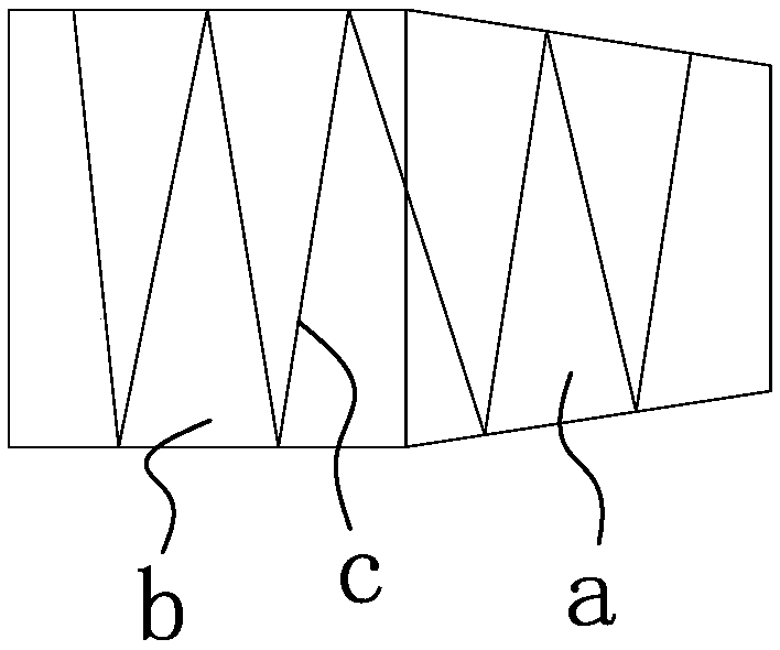
[0075] The structure and principle of this embodiment are basically the same as those of the first embodiment, so they will not be repeated here. The difference lies in the fact that an electrified coil c is sheathed on the outside of the tapered section a.


PUM


Abstract

The invention belongs to the technical field of accelerometers, particularly relates to a magnetizing device and magnetizing method for a six-sided magnetic suspension body and aims at solving the problem of unreasonable design in the prior art. The magnetizing device for the six-sided magnetic suspension body comprises a vertically arranged lower magnetizing head, an upper magnetizing head located above the lower magnetizing head, and four lateral surface magnetizing heads which are distributed along the circumference and are horizontally arranged, wherein the lateral surface magnetizing heads are located between the lower magnetizing head and the upper magnetizing head; a first magnetizing contact plane is arranged at the upper end of the lower magnetizing head; a second magnetizing contact plane parallel to the first magnetizing contact plane is arranged at the lower end of the upper magnetizing head; and a vertically arranged third magnetizing contact plane is arranged at the innerend of each lateral surface magnetizing head. The magnetizing device and the magnetizing method have the advantages that the method is simple, and simultaneous magnetization of six sides can be completed once, so that the magnetization efficiency can be improved.

Description

technical field [0001] The invention belongs to the technical field of accelerometers, and in particular relates to a magnetizing device and a magnetizing method for a six-sided magnetic levitation body. Background technique [0002] Traditional accelerometers usually use a spring vibrator to sense acceleration changes, but due to the physical contact between the vibrator and the spring, it will be affected by factors such as mechanical structure performance and friction and cannot fully reflect the real acceleration input. In order to overcome this technical problem, countries all over the world have spared no effort to carry out research on various suspension accelerometers. Because there is no physical contact, they can fully reflect real acceleration changes, which is beneficial to improve accuracy and reduce volume. [0003] In the prior art, there is no magnet with remanent magnetic fields on all six sides. Of course, the same hexahedral solid permanent magnet material...

Claims


Application Information

Patent Timeline
Patent Type & Authority Applications(China)
IPC IPC(8): H01F13/00
CPCH01F13/00H01F13/003
Inventor 周继军吴建锋郑梁
Owner 徐州新南湖科技有限公司
Why Eureka
Try Eureka