
Control circuit of magnetized liquid device

A technology of magnetizing liquid and control circuit, applied in the fields of magnetic field/electric field water/sewage treatment, etc., can solve the problems of easy damage of control circuit components, affecting the cost of magnetizing liquid, shortening the life of magnetizing liquid device, etc.

Inactive Publication Date: 2007-05-23
蔡志峰
View PDF0 Cites 2 Cited by
  • Summary
  • Abstract
  • Description
  • Claims
  • Application Information

AI Technical Summary

Problems solved by technology

In addition, the known control circuit components are easy to damage, especially when the magnetization frequency is high, it is easy to cause overvoltage problems with the change of the material of the selected flow guide components, which will shorten the life of the magnetized liquid device, and often have to withstand Transistors with higher voltage values ​​also indirectly affect the cost of magnetizing liquids

Method used


Image

  • Control circuit of magnetized liquid device
  • Control circuit of magnetized liquid device
  • Control circuit of magnetized liquid device

Examples


Embodiment Construction

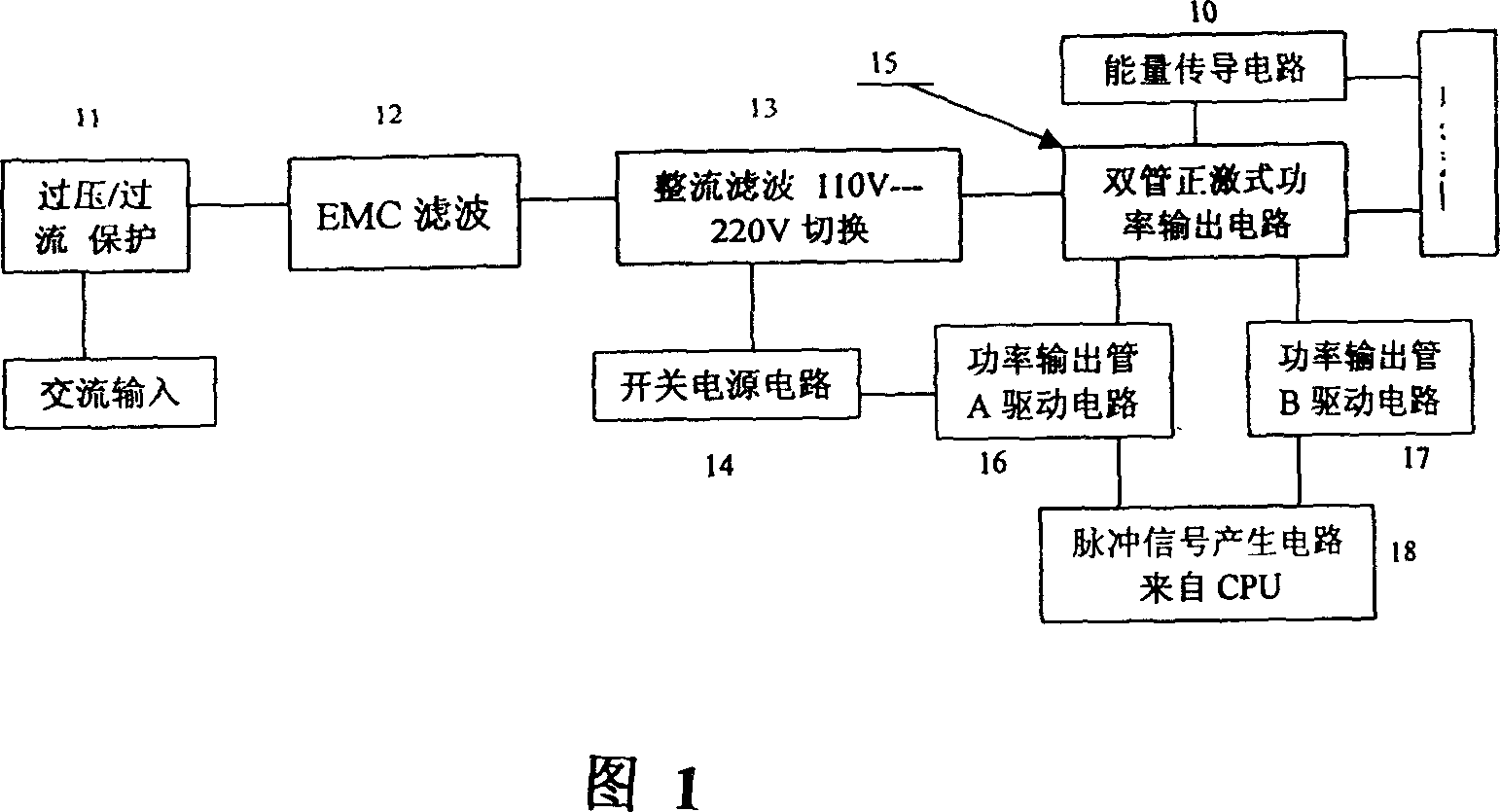
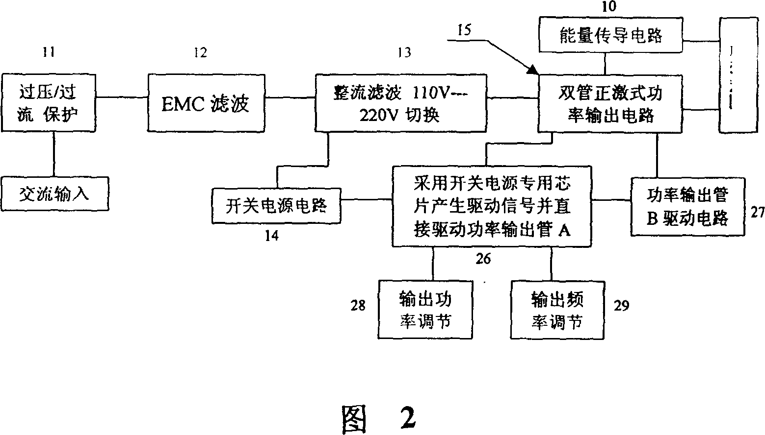
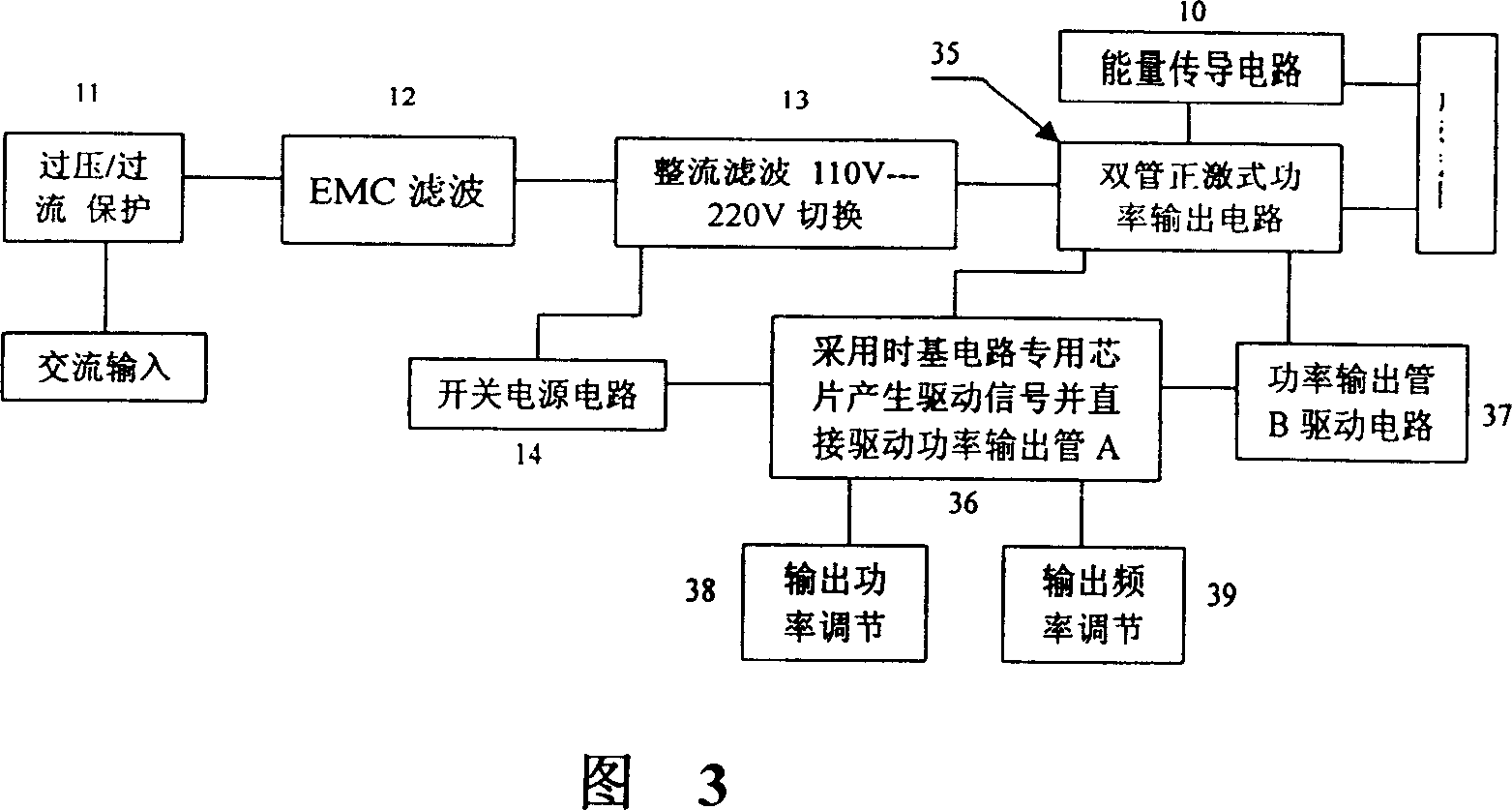
[0041] Please refer to FIGS. 1 and 5, which respectively show a block diagram and a schematic circuit diagram of an embodiment of a control circuit using a CPLD (Programmable Logic Device) chip to drive a two-transistor forward inverter according to the present invention.

[0042] In Fig. 1, the AC power of 110V or 220V is input to the overcurrent / overvoltage protection circuit 11, passed through the electromagnetic compatibility (EMC) filter circuit 12, and then applied to the rectification and filter circuit 13 to convert the input AC power into DC power, The rectification and filtering circuit 13 further includes a 110V / 220V switching switch, so that the input AC power can be switched to 220V or 110V.

[0043] Figure 5 shows that the overcurrent / overvoltage protection circuit 11 can be composed of a fuse (fuse) and a voltage sensitive element (ZMR), the EMC filter circuit 12 can be composed of capacitors C1 and C2 and a choke coil (choke) L1, and a rectification and filter c...


PUM


Abstract

The invention is about a pilot circuit of liquid magnetizing device which includes rectifying and filter circuit, switch circuit, energizing circuit and energy-conducting circuit. The switch circuit contains at least one power transistor, every power transistor works in on and off state, during the period when the power transistor is broken-over; the pulse power source is exerted to the magnet exciting coil. The characteristic of the circuit: when the power transistor changes from break-over to cut-off, the energy stored in the magnetic field goes back to the filtering capacitance, when the power transistor is broken-over again, the electric charges is utilized again to become the magnetic energy in the coil so the invention has quite little energy expenditure. The advantages of the invention: the pulse magnetic field in the invention can improve the magnetizing efficiency and decrease the energy expenditure; the control circuit in the invention can decrease the consumed power in pilot circuit, extend the service life of the pilot circuit as well as decrease the cost.

Description

technical field [0001] This invention relates to control circuits, in particular to control circuits for magnetized liquid devices. Background technique [0002] The magnetized liquid has been widely used in various fields because of its smaller molecular clusters, higher penetration, solubility, oxygen content, and conductivity than the liquid before magnetization. Magnetized water is the main For example, it has the advantages of dissolving scale and increasing the yield of agricultural products. [0003] Traditional devices for magnetizing liquids usually use permanent magnets, DC fixed magnetic fields, power frequency alternating magnetic fields, or quasi-resonant alternating magnetic fields to magnetize liquids. [0004] However, the magnetization device using permanent magnets, DC fixed magnetic fields, and power frequency alternating magnetic fields has a large volume, and the magnetic field strength of the permanent magnets is invariable. Although the magnetic field...

Claims


Application Information

Patent Timeline
IPC IPC(8): C02F1/48H02M9/00H02M9/02
Inventor 蔡志峰
Owner 蔡志峰
Learn More