On-site cooperation method for power supply operation based on augmented reality device

A job site, augmented reality technology, applied in measuring devices, TVs, color TVs, etc., can solve the problem of lack of an effective and reliable power supply operation site coordination and control method, saving preparation time, saving time, and accurate identification. high degree of effect

Inactive Publication Date: 2018-04-13
STATE GRID ZHEJIANG HANGZHOU XIAOSHAN POWER SUPPLY CO +3
View PDF4 Cites 4 Cited by
  • Summary
  • Abstract
  • Description
  • Claims
  • Application Information

AI Technical Summary

Problems solved by technology

Some places use more advanced on-site collaborative management and control technologies such as video and group chat, but they still rely on the job site an

Method used


Image

  • On-site cooperation method for power supply operation based on augmented reality device
  • On-site cooperation method for power supply operation based on augmented reality device
  • On-site cooperation method for power supply operation based on augmented reality device

Examples


Embodiment 1

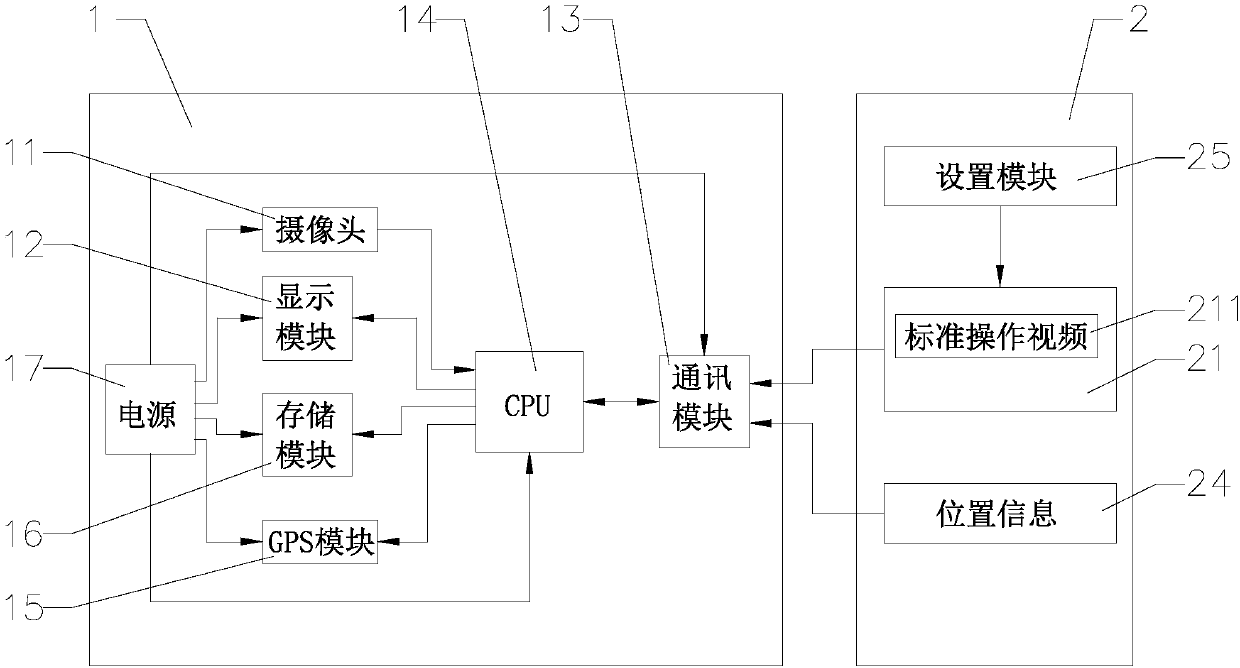
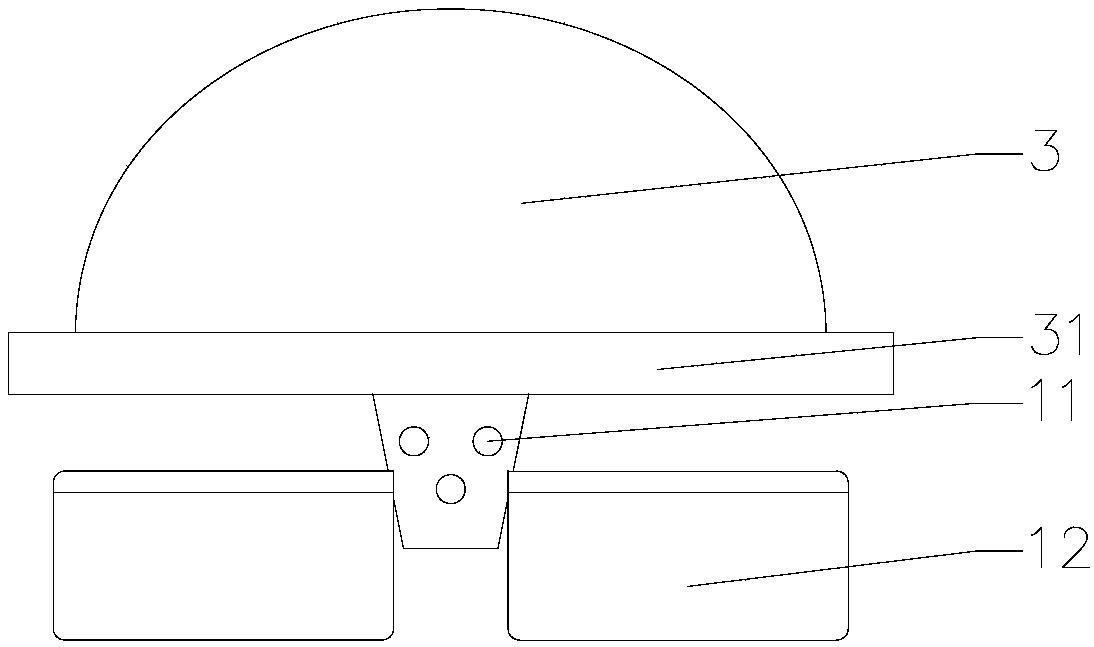
[0039] Such as Figures 1 to 3As shown, the present invention provides a power supply operation site collaboration method based on an augmented reality device. The augmented reality device includes AR glasses 1 and a mobile terminal 2. The AR glasses 1 are provided with a camera 11 based on augmented reality technology for projecting 3D video Display module 12, communication module 13 and CPU14, camera 11, display module 12 and communication module 13 are electrically connected with CPU14 respectively, and CPU14 is connected mobile terminal 2 through communication module 13, and mobile terminal 2 is provided with standard operation video 211, and inside CPU14 A first error value is set. In this embodiment, the CPU is Qualcomm Snapdragon 660 processor, which has stable performance and fast processing speed, ensuring the reliability of the augmented reality device. The power supply operation site collaboration method includes at least the following steps:

[0040] Receiving tas...

Embodiment 2

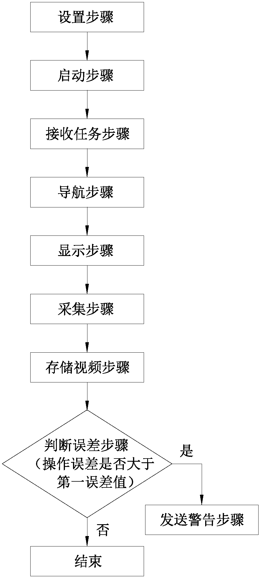
[0058] Such as Figures 4 to 5 As shown, the main difference between this embodiment and Embodiment 1 is that the power supply operation site collaboration method further includes an analysis step and a storage step.

[0059] The mobile terminal 2 is also provided with a model conversion center 22, the model conversion center 22 is electrically connected to the CPU 14, and the power supply operation site collaboration method includes the following steps:

[0060] Setting step: customize a suitable standard operation video 211 through the setting module 25, and transmit the standard operation video 211 to the video library 21;

[0061] Starting step: start the power supply 17, so that the power supply 17 is divided into AR glasses 1 to supply power;

[0062] Steps of receiving the task: the mobile terminal 2 transmits the standard operation video 211 to the CPU 14;

[0063] Navigation step: the GPS module 15 locates the specific location of the staff, and performs navigation ...


PUM


Abstract

The invention provides an on-site cooperation method for power supply operation based on an augmented reality device, which at least comprises the following steps of: a task receiving step: a mobile terminal transmits a standard operation video to a CPU; a display step: the CPU transfers the standard operation video to a display module, and the display module projects and displays the standard operation video; an acquisition step: a camera performs longitudinal scanning to collect a operator's operating scene; an error determination step: the camera transmits the acquired operation scene to the CPU, and the CPU compares the operation scene with the standard operation video information and judges whether the operation error between the two is greater than a first error value; and a warningsending step: if the operation error is greater than the first error value, the CPU sends a warning signal to the display module, and the warning signal is displayed through the display module, so that the operator can timely know that his own operation is not standardized, and corrects his operation compared with the standard operation video, to achieve effective coordination and control of the power supply operation site, and to improve the quality of the power supply operation.

Description

technical field [0001] The invention relates to a power supply operation site coordination method, in particular to a power supply operation site coordination method based on an augmented reality device. Background technique [0002] The current power supply operation site still uses paper or ordinary electronic manuals as the guidance method, and most of them rely on the operation skills, habits and sense of responsibility of the on-site operators to control the operation. Some places use more advanced on-site collaborative management and control technologies such as video and group chat, but they still rely on the job site and collaborative personnel's skills, habits, and sense of responsibility, and there is no effective and reliable method for power supply job site collaboration and control. Contents of the invention [0003] The purpose of the present invention is to provide a power supply operation site collaboration method based on an augmented reality device, which...

Claims


Application Information

Patent Timeline
IPC IPC(8): H04N13/243H04N13/363H04N13/332H04N7/18H04N5/76H04N5/93G01S19/13
CPCH04N7/18G01S19/13H04N5/76H04N5/93
Inventor 黄一鸣张晓炎吴振杰谭卓强杨慧许金彤姚衍民翁利国俞晖徐勤沈立新罗海锋孙建娣王龙杨军高瑾
Owner STATE GRID ZHEJIANG HANGZHOU XIAOSHAN POWER SUPPLY CO
Why Eureka
Try Eureka