Dynamic loading device of railway locomotive drive component

A driving component and dynamic loading technology, which is applied in the testing of machine/structural components, measuring devices, railway vehicle testing, etc., to achieve the effects of increasing safety and stability, saving materials, and facilitating installation

Active Publication Date: 2015-04-29
CRRC QISHUYAN INSTITUTE CO LTD
View PDF8 Cites 25 Cited by
  • Summary
  • Abstract
  • Description
  • Claims
  • Application Information

AI Technical Summary

Problems solved by technology

[0007] The purpose of the present invention is to provide a dynamic loading device for the driving parts of railway locomotives, which can effectively solve the problem of imposing the upper transverse and vertical e

Method used


Image

  • Dynamic loading device of railway locomotive drive component
  • Dynamic loading device of railway locomotive drive component
  • Dynamic loading device of railway locomotive drive component

Examples


Embodiment Construction

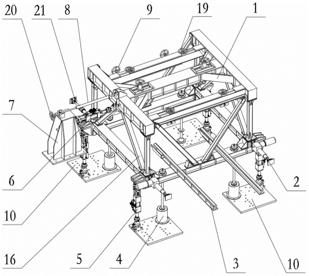
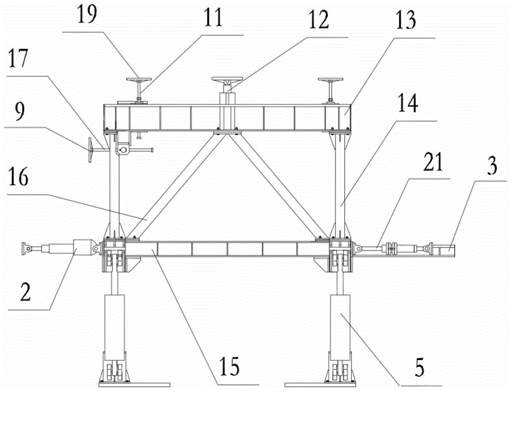
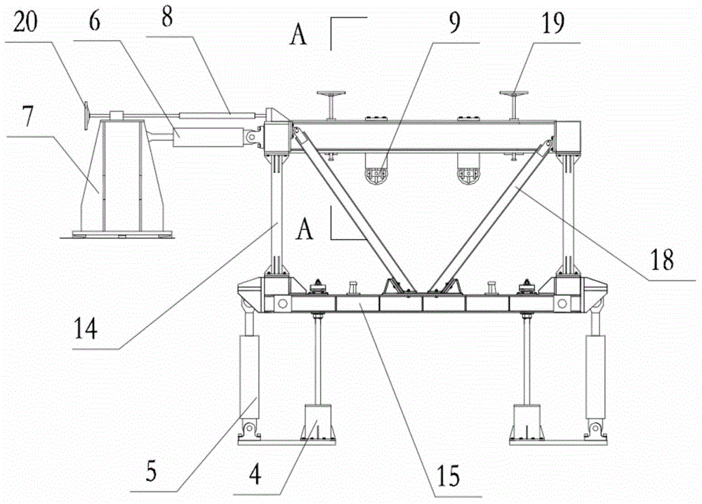
[0063] The present invention will be further described below by accompanying drawing:

[0064] A dynamic loading device for a driving part of a railway locomotive, comprising a vertical oil cylinder 5 and a transverse oil cylinder 6 arranged on a mounting plate 10 and connected to a loading frame 1 . Both ends of the vertical oil cylinder 5, the horizontal oil cylinder 6 and the longitudinal electric push-pull rod 2 are provided with ball hinges, one end of the vertical oil cylinder 5 is fixed to the mounting plate 10, and the other end of the ball hinge seat is connected to the lower frame 15, One end of the horizontal oil cylinder 6 is connected to the horizontal reaction force frame 7, and the other end is connected to the left side beam 23 of the upper frame 13; The two ends of the side beams are connected, and the ball hinge seats at one end of the two limit push-pull rods 21 are respectively connected with the two ends of the rear side beam of the lower frame 15; the spr...


PUM


Abstract

The invention discloses a dynamic loading device of a railway locomotive drive component and belongs to the field of locomotive engineering tests. The two ends of vertical oil cylinders, the two ends of transverse oil cylinders, the two ends of longitudinal electric locating push-and-pull rods and the two ends of limiting push-and-pull rods are each provided with a ball hinge. One end of each vertical oil cylinder, one end of each transverse oil cylinder, one end of each longitudinal electric locating push-and-pull rod and one end of each limiting push-and-pull rod are connected with a cage-shaped loading frame, and the other end of each vertical oil cylinder, the other end of each transverse oil cylinder, the other end of each longitudinal electric locating push-and-pull rod and the other end of each limiting push-and-pull rod are connected to a base. The six-freedom-degree movement of the loading frame can be controlled. An upper frame of the loading frame is provided with a special connector and can be rapidly connected with a simulation steering frame with the tested drive component, in this way, dynamic loading can be effectively conducted on the drive component installed in the steering frame, and the vibration working environment and the stress working environment of the drive component are simulated. The dynamic loading device is suitable for different tested drive components through the fixed structure, the problem that oil cylinders are frequently dismounted and mounted is solved, a workload is reduced, the oil cylinders are loaded in a tensioned mode, and meanwhile spring struts are connected in parallel to complete loading of vertical static component force. The dynamic loading device of the railway locomotive drive component is mainly used for load testing of the railway locomotive drive component.

Description

technical field [0001] The invention belongs to the technical field of railway locomotive engineering, and in particular relates to a loading test technology of a driving part of a railway locomotive. Background technique [0002] With the increase of the speed and power of the traction motor, the axle drive system of railway locomotives has become the key link to determine the reliability of the locomotive. It is necessary to establish a special test bench to realize the dynamic vibration loading simulation environment of the axle drive system of high-power locomotives, and to carry out experimental research . [0003] At present, the test benches that can provide a dynamic loading environment for wheel axle drives include the wheel-rail relationship test bench of the Institute of Railway Sciences, which can provide an interface for simulating rails with irregularities. The dynamic axle load environment is formed by the thrust provided by the gantry and the hydraulic cylin...

Claims


Application Information

Patent Timeline
IPC IPC(8): G01M17/08G01M7/02
Inventor 林新海周文祥靳国忠马玉强王晓博张进
Owner CRRC QISHUYAN INSTITUTE CO LTD
Why Eureka
Try Eureka