A common rail injector control valve

A common rail injector and control valve technology, which is applied to fuel injection devices, machines/engines, charging systems, etc., can solve the problems of difficulty in increasing injection pressure, slow reduction in fuel pressure, and reducing fuel system economy. The effect of reducing leakage and fuel injection delay

Active Publication Date: 2020-04-07
CHINA FIRST AUTOMOBILE
View PDF12 Cites 0 Cited by
  • Summary
  • Abstract
  • Description
  • Claims
  • Application Information

AI Technical Summary

Problems solved by technology

With the increase of the fuel injection pressure of the common rail system, the leakage of the fuel injector will increase significantly, which will cause the power loss of the common rail system to be obvious, the efficiency will decrease, and the economy of the fuel system will be reduced
At the same time, more high-pressure fuel leaks into the low-pressure oil circuit, which will lead to a higher temperature of the low-pressure oil circuit in the injector, which will affect the stability and reliability of the injector, making it difficult to increase the injection pressure.
[0004] In addition, in order to reduce the closing delay of the fuel injector in the design of the fuel injector, the flow rate of the fuel outlet hole and the oil inlet hole of the fuel injector should not be larger than the designed one.
This causes the fuel pressure in the control chamber to decrease slowly, resulting in a slow decrease in the fuel pressure in the control chamber at the beginning of fuel injection, and a longer delay in opening the injector, resulting in poor fuel injection sensitivity of the injector , which limits the improvement of the injector's multiple injection capability

Method used


Image

  • A common rail injector control valve
  • A common rail injector control valve
  • A common rail injector control valve

Examples


Embodiment Construction

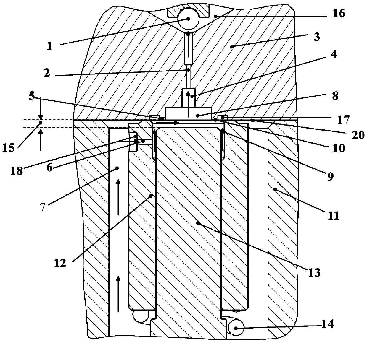
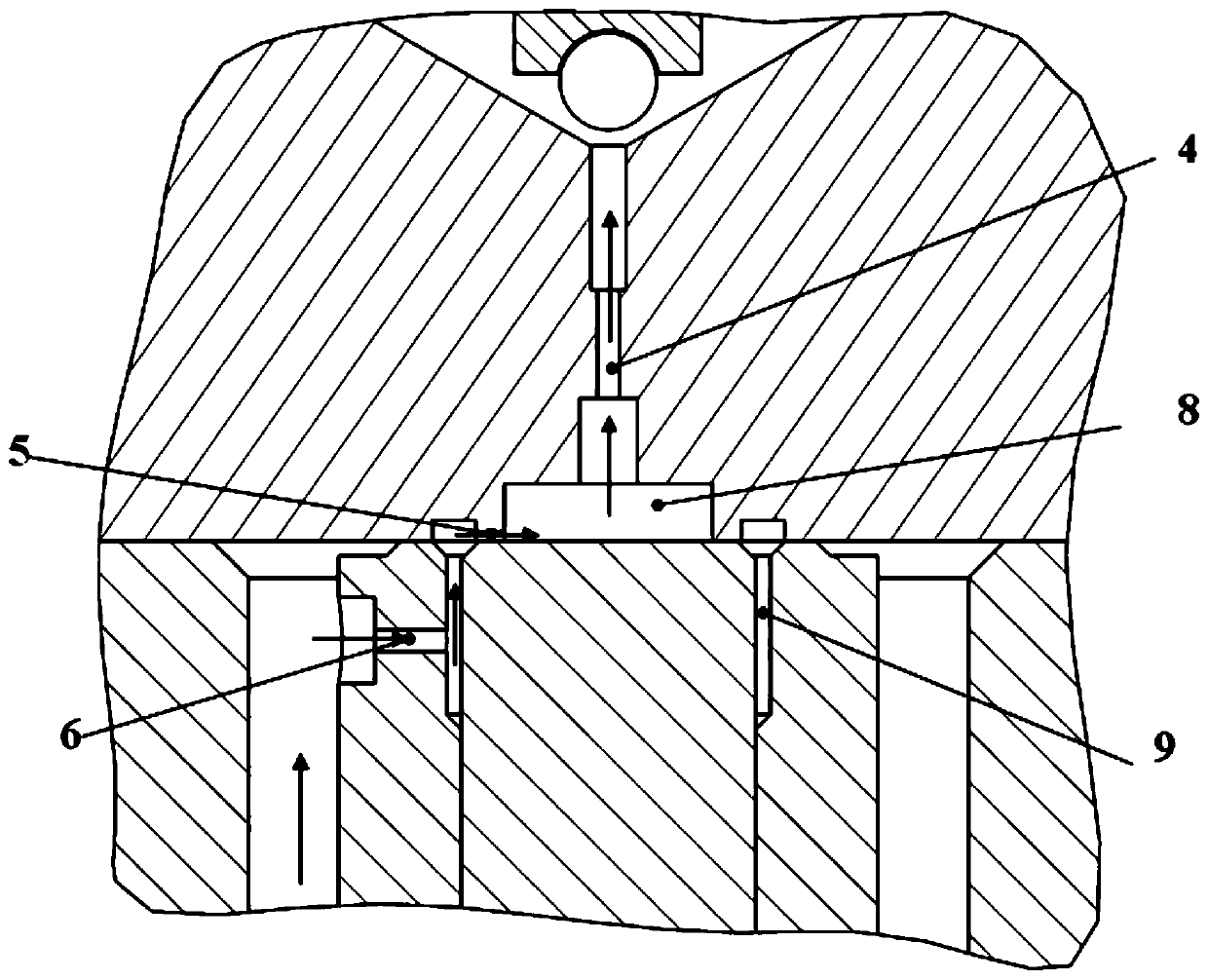
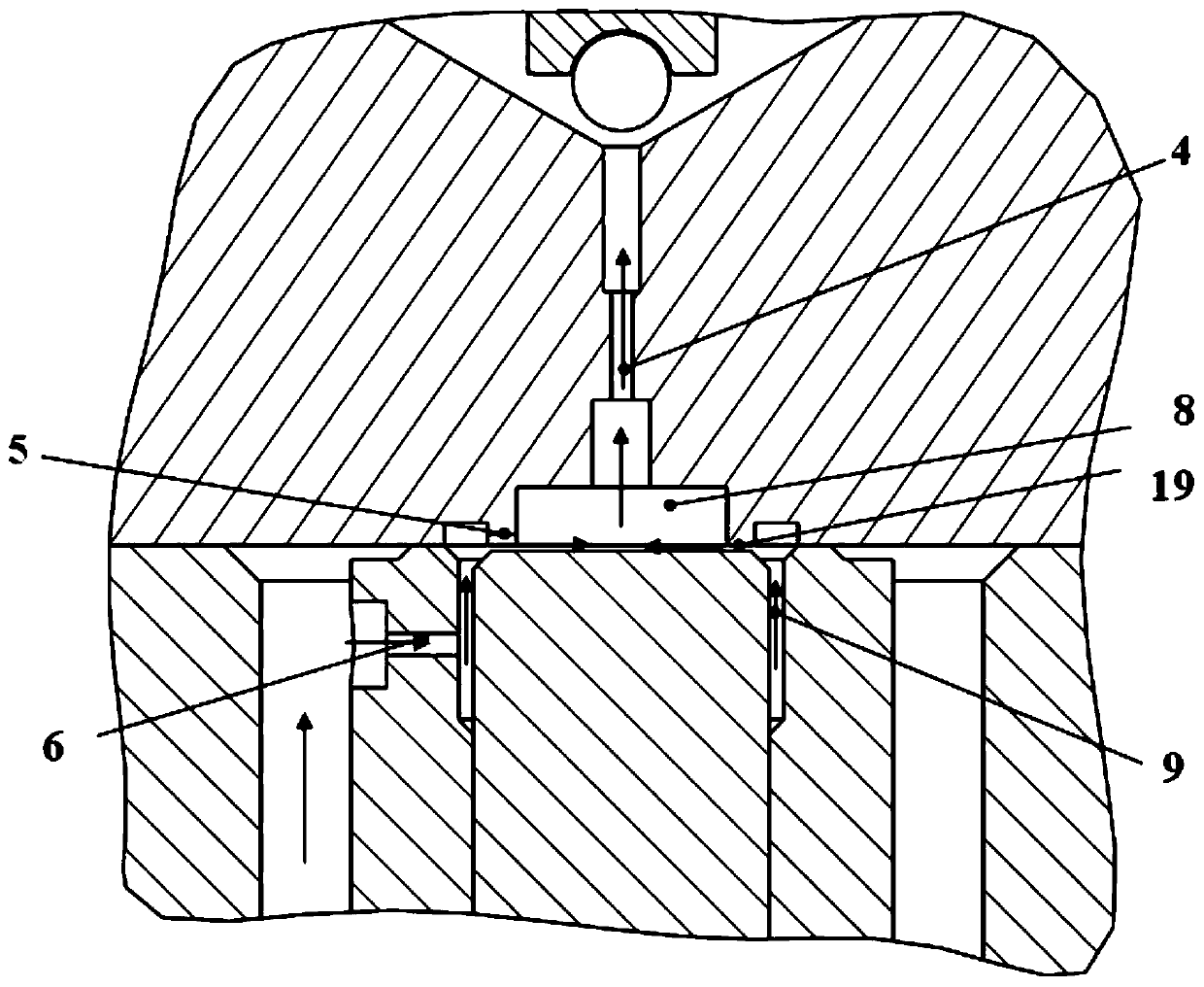
[0025] A kind of common rail fuel injector of the present invention can refer to attached figure 1 , 2 , 3, 4, and 5 descriptions.

[0026] A new type of common rail injector control valve, including injector body 11, orifice plate 3, control piston 13, floating sleeve 12 and preload spring 14; control piston 13, preload spring 14, floating sleeve 12 are located In the oil chamber 7. An oil return passage 16 is arranged inside the orifice plate 3 , and the connection between the oil return passage 16 and the low-pressure oil passage is opened or closed by the sealing surface and the ball valve 1 . The top of the control piston 13 is located in the inner cavity of the floating sleeve 12 . The inner cavity of the floating sleeve 12 has a stepped inner cylindrical surface, the top diameter of the inner cavity is larger than the bottom, and the bottom cylindrical surface matches the top cylinder of the control piston 13, and one end of the floating sleeve 12 is connected to the...


PUM


Abstract

The invention discloses a control valve for a common-rail oil injector. According to the control valve, when a control piston ascends and descends, a high-pressure oil cavity communicates with a low-pressure oil passage through an oil cavity B, a throttling ring belt between a sealing ring surface and the top plane of the control piston, a throttling groove in the sealing ring surface and an oil cavity A, wherein the oil cavity A and the oil cavity B in the oil passage are connected in series; in the ascending process of the control piston, the throttling effect of the throttling ring belt canbe continuously increased, the leakage amount can be effectively decreased, meanwhile, the flow ratio of an oil outlet quantity hole to an oil inlet quantity hole can be larger, the time when the control piston ascends can be earlier, and the oil spraying delay can be reduced; and after the control piston lift reaches the maximum value, the oil cavity A and the oil cavity B are connected throughthe throttling groove only, the flowing resistance can be improved, the leakage amount can be decreased, the oil cavity B can be kept higher pressure, when an electromagnetic valve is powered off, thepressure of a control cavity can be restored faster, the oil injection delay of the oil injector can be reduced, meanwhile, the closing delay can be reduced, and the oil injection sensitivity of theoil injector can be improved.

Description

technical field [0001] The invention belongs to the field of fuel injection systems of internal combustion engines, and in particular relates to a control valve of a common rail fuel injector. Background technique [0002] From the working principle of the common rail injector, it can be seen that the movement of the armature is controlled by the solenoid valve to control the change of the fuel pressure in the control chamber, so as to control the force of the pressure difference between the upper and lower pistons, and realize the control of fuel injection and seating of the control piston. And the control chamber has an oil inlet orifice and an oil outlet orifice, the oil inlet orifice is connected to the high pressure oil passage, and the oil outlet orifice is connected to the low pressure oil passage, such as patents CN102282354A, CN201210199068.8, CN200820014041. 6. [0003] During the fuel injection process, both the inlet and outlet orifices are open, and the high-pr...

Claims


Application Information

Patent Timeline
Patent Type & Authority Patents(China)
IPC IPC(8): F02M61/16F02M61/18F02M63/00
CPCF02M61/16F02M61/1853F02M61/1893F02M63/0017F02M63/0056F02M63/0078
Inventor 郭立新周禛徐世龙施东晓李康宁
Owner CHINA FIRST AUTOMOBILE
Why Eureka
Try Eureka