
Auxiliary device of cable test

An auxiliary device and cable test technology, applied in the direction of the measuring device shell, fault location, clamping/spring connection, etc., can solve the problem of reducing work efficiency and rushing to repair electricity time, unstable, affecting work progress, and testing work safety test data Accuracy and other issues to achieve the effect of improving work efficiency and safety, and increasing operating space

Pending Publication Date: 2018-04-17
QINGYUAN POWER SUPPLY BUREAU OF GUANGDONG POWER GRID CO LTD
View PDF8 Cites 1 Cited by
  • Summary
  • Abstract
  • Description
  • Claims
  • Application Information

AI Technical Summary

Problems solved by technology

[0002] During the implementation of the 10 kV cable test, it is often encountered that the connection between the test line and the cable core of the outdoor terminal head of the 10 kV cable distribution box is difficult and not firm, which not only affects the work progress, the safety of the test work and the accuracy of the test data, but also affects the accuracy of the test data. It will cause irreparable damage to the accessories of the outdoor terminal head of the 10 kV cable, leaving hidden defects and affecting the safe and stable operation of the cable
And the grounding test terminal is short and small, placed in the T-shaped joint hole, it is not convenient for the lap connection of the test line, which increases the work difficulty of the staff, reduces the work efficiency and the repair time, and is inconvenient to use

Method used


Image

  • Auxiliary device of cable test

Examples


Embodiment

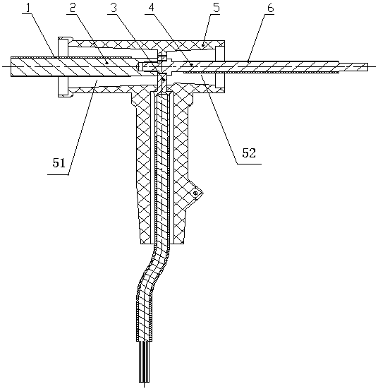
[0020] Such as figure 1 Shown is an embodiment of a 10 kV cable test auxiliary device. The auxiliary device includes a joint insulation layer 1, a threaded joint 2, a cable lug 3, an auxiliary terminal 4, a T-shaped joint 5, a terminal insulation layer 6, and a joint insulation layer 1 Wrapped on the outside of the threaded joint 2, one end of the threaded joint 2 is provided with a threaded hole 21, and the end of the cable lug 3 fits with the end of the threaded hole 21; the auxiliary terminal 4 matches the threaded hole 21; the cable lug 3 It is clamped with the T-shaped joint 5 , and the terminal insulation layer 6 is wrapped on the outside of the T-shaped joint 5 .

[0021] Wherein, the T-shaped joint 5 is provided with a first air cylinder 51 and a second air cylinder 52 , the auxiliary terminal 4 is installed on one side of the second air cylinder 52 , and the threaded joint 2 is arranged on one side of the first air cylinder 51 .

[0022] In addition, part of the surf...


PUM


Abstract

The invention relates to an auxiliary device of cable test, and belongs to the field of mechanical structures. The auxiliary device comprises a joint insulation layer, a threaded joint, a cable lug, an auxiliary terminal, a T type joint and a terminal insulation layer; the joint insulation layer wraps the threaded joint, one end of the threaded joint is provided with a threaded hole, and the end portion of the cable lug is fit to the end portion of the threaded hole; the auxiliary terminal cooperates with the threaded hole; and the cable lug is in clamp connection with the T type joint, and the terminal insulation layer wraps the T type joint. According to the auxiliary device of 10kV cable test, the operation space is increased to overcome problems that terminals are short and small and the operation space is narrow in original grounding test, and thus, operation staff can improve the working efficiency and safety effectively.

Description

technical field [0001] The invention belongs to the field of mechanical structures, and more specifically relates to a cable test auxiliary device. Background technique [0002] During the implementation of the 10 kV cable test, it is often encountered that the connection between the test line and the cable core of the outdoor terminal head of the 10 kV cable distribution box is difficult and not firm, which not only affects the work progress, the safety of the test work and the accuracy of the test data, but also affects the accuracy of the test data. It will cause irreparable damage to the accessories of the outdoor terminal head of the 10 kV cable, leaving hidden defects and affecting the safe and stable operation of the cable. And the grounding test terminal is relatively short and small, placed in the T-shaped joint hole, which is not convenient for the lap connection of the test line, increases the work difficulty of the staff, reduces work efficiency and rush repair t...

Claims


Application Information

Patent Timeline
Patent Type & Authority Applications(China)
IPC IPC(8): G01R31/08G01R1/04H01R4/30
CPCH01R4/30G01R1/04G01R31/08
Inventor 刘惠玲范平涛冯颖君黄耀亮杨勇冯世伟梁润宇陈江
Owner QINGYUAN POWER SUPPLY BUREAU OF GUANGDONG POWER GRID CO LTD
Learn More