Automatic loading and unloading system for logistics robot

A logistics robot, automatic loading and unloading technology, applied in the direction of loading/unloading, transportation and packaging, conveyor objects, etc., can solve the problems of unable to meet the high-efficiency requirements of logistics transportation, irregular cargo application scenarios, and unsatisfactory loading and unloading space, etc., to achieve the path The effect of convenient planning, overcoming irregular clothing unloading space and simple structure

Inactive Publication Date: 2020-01-07
GUANGZHOU UNIVERSITY
View PDF10 Cites 8 Cited by
  • Summary
  • Abstract
  • Description
  • Claims
  • Application Information

AI Technical Summary

Problems solved by technology

[0002] In the current logistics and transportation market, the loading of cargo containers still needs to be done manually, which is time-consuming and laborious, and cannot meet the efficient needs of logistics and transportation.
There are two existing automatic loading and unloading systems, one is the automatic storage system, which is aimed at regularized goods and regularized shelves, which cannot meet the application scenarios of irregular goods, unfixed positions, and no shelf palletizing in the logistics industry; the other An automatic loading and unloading system is a system that is applied to the robotic arm of the assembly line to pick up and load goods. It is aimed at the application of a single cargo in a fixed space, and it cannot meet the needs of the logistics field where the loading and unloading space is mobile and the goods are irregular. Application Scenario

Method used


Image

  • Automatic loading and unloading system for logistics robot
  • Automatic loading and unloading system for logistics robot
  • Automatic loading and unloading system for logistics robot

Examples


Embodiment Construction

[0023] The present invention will be further described in detail in conjunction with the accompanying drawings and specific embodiments.

[0024] In order to facilitate a unified review of the various reference signs in the drawings of the specification, the unified description of the reference signs appearing in the drawings of the specification is as follows:

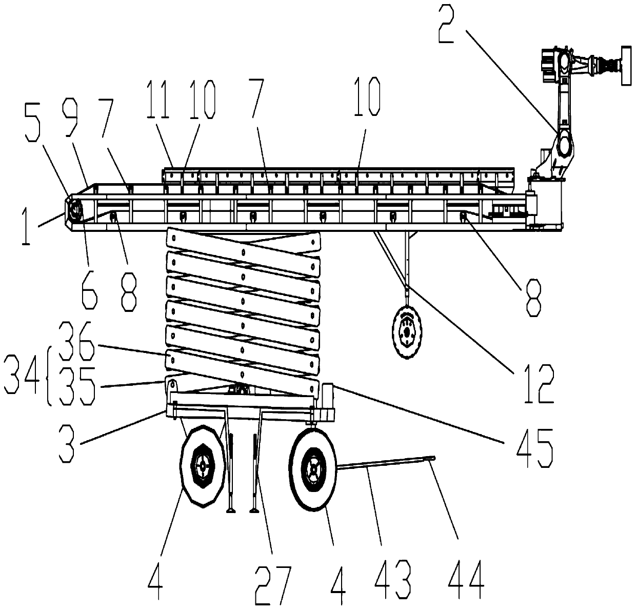
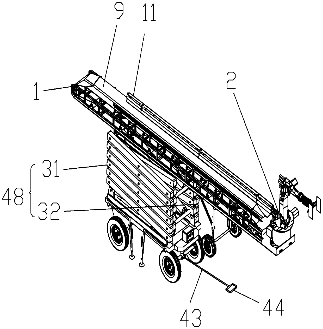
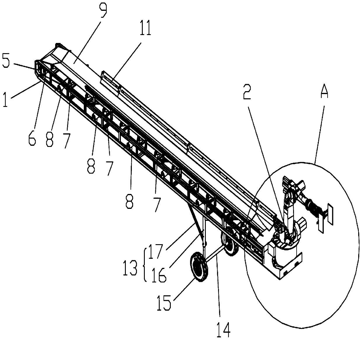
[0025] 1 is the bracket, 2 is the loading and unloading mechanical arm mechanism, 3 is the bottom plate, 4 is the wheel, 5 is the driving motor, 6 is the driving wheel, 7 is the driven wheel, 8 is the tightening wheel, 9 is the feeding belt, 10 is the support column, 11 12 is a hydraulic support mechanism, 13 is a hydraulic support group, 14 is a straight shaft, 15 is a support wheel, 16 is a support hydraulic cylinder, 17 is a reinforcement rod, 18 is a support plate, 19 is a base, 20 is a turntable, 21 is the first servo motor, 22 is the second servo motor, 23 is the first swing arm, 24 is the second swing arm, 25 i...


PUM


Abstract

The invention relates to an automatic loading and unloading system for a logistics robot, and belongs to the technical field of logistics application robots. The system comprises a transport mechanism, a lifting mechanism mounted on the conveying mechanism, a bracket mounted on the lifting mechanism, a conveying mechanism and a loading and unloading mechanical arm mechanism, wherein the conveyingmechanism and the loading and unloading mechanical arm mechanism are mounted on the bracket. A part of the bracket is mounted on the lifting mechanism, the rest of the bracket is suspended, and the loading and unloading mechanical arm mechanism is mounted at the tail end of the suspended part of the bracket. The conveying mechanism comprises a driving motor mounted on the bracket, a driving wheelmounted at the output end of the driving motor, a driven wheel, a tightening wheel and a conveying belt, wherein the driven wheel and the tightening wheel are rotatably mounted on the bracket, and thefeeding belt sleeves the driving wheel and the driven wheel. The tightening wheel is located below the feeding belt and extrudes the lower surface of the belt, supporting columns and guardrail beltsare arranged on the two sides of the bracket, the supporting columns are fixed to the bracket, the guardrail belts are fixed to the supporting column, and the guardrail belts are located on the two sides of the feeding belt. The system can realize automatic loading and unloading on containers and cargo vehicles.

Description

technical field [0001] The invention relates to the technical field of logistics robots, in particular to an automatic loading and unloading system for logistics robots. Background technique [0002] In the current logistics and transportation market, the loading of cargo containers still needs to be done manually, which is time-consuming and laborious, and cannot meet the efficient needs of logistics and transportation. There are two existing automatic loading and unloading systems, one is the automatic storage system, which is aimed at regularized goods and regularized shelves, which cannot meet the application scenarios of irregular goods, unfixed positions, and no shelf palletizing in the logistics industry; the other An automatic loading and unloading system is a system that is applied to the robotic arm of the assembly line to pick up and load goods. It is aimed at the application of a single cargo in a fixed space, and it cannot meet the needs of the logistics field w...

Claims


Application Information

Patent Timeline
Patent Type & Authority Applications(China)
IPC IPC(8): B65G41/00B65G47/90B65G67/04B65G67/24
CPCB65G41/003B65G41/008B65G47/90B65G67/04B65G67/24
Inventor 刘元恒艾山陈晓聪方中阳
Owner GUANGZHOU UNIVERSITY
Why Eureka
Try Eureka