
Automatic punch feeder with high conveying efficiency

An automatic feeding and high-efficiency technology, applied in metal processing equipment, feeding devices, forming tools, etc., can solve the problems of low stamping accuracy and low feeder efficiency, and achieve reduced friction, improved stamping efficiency, and improved stamping accuracy. Effect

Inactive Publication Date: 2018-04-20
秦科
View PDF6 Cites 1 Cited by
  • Summary
  • Abstract
  • Description
  • Claims
  • Application Information

AI Technical Summary

Problems solved by technology

[0004] The purpose of the present invention is to provide an automatic punch feeder with high transmission efficiency. The technical problem to be solved is: the feeder has the problem of low efficiency and low punching accuracy

Method used


Image

  • Automatic punch feeder with high conveying efficiency

Examples


Embodiment Construction

[0014] The principles and features of the present invention are described below in conjunction with the accompanying drawings, and the examples given are only used to explain the present invention, and are not intended to limit the scope of the present invention.

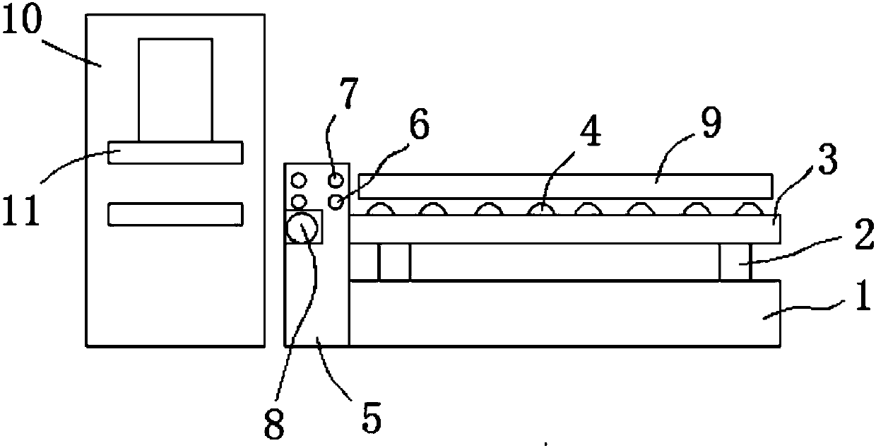
[0015] Such as figure 1 As shown, a punch automatic feeder with high transmission efficiency includes a feed frame 1, the upper end of the feed frame 1 is provided with a jacking device 2, and the upper end of the jacking device 2 is provided with a lifting platform 3 , the jacking device 2 can drive the lifting platform 3 to move vertically; the lifting platform 3 is provided with a plurality of first rolling rollers 4 that drive the material to move horizontally;

[0016] One side of the lifting table 3 is provided with a console 5, and the upper inner side of the console 5 is provided with a feed roller 6 and a nip roller 7, and the nip roller 7 is above the feed roller 6; The feed roller 6 and the first rolling...


PUM


Abstract

The invention relates to an automatic punch feeder with high conveying efficiency. The automatic punch feeder with the high conveying efficiency comprises a feeding rack; a jacking device is arrangedat the upper end of the feeding rack, and a lifting table is arranged at the upper end of the jacking device; the lifting table is provided with a plurality of first rolling rollers; a console is arranged on one side of the lifting table; a feeding roll and a pressing roll are arranged on the inner side of the upper portion of the console, and the pressing roll is located above the feeding roll; astepping motor is arranged on the inner side of the lower portion of the console, and an output shaft of the stepping motor is connected with the multiple first rolling rollers, the feeding roll andthe pressing roll; a punch is arranged on the side, away from the lifting table, of the console, and a die is arranged at the position, corresponding to the feeding roll, in the punch; two limiting baffles are arranged above the multiple rolling rollers and form a limiting channel above the multiple rolling rollers; and idler wheels are arranged on the sides, close to each other, of the two limiting baffles. According to the automatic punch feeder with the high conveying efficiency, the structure is simple, raw material parts are conveyed in a limited mode, the punching precision is improved,and the conveying efficiency is improved.

Description

technical field [0001] The invention relates to a processing machine, in particular to an automatic feeder for a punching machine with high transmission efficiency. Background technique [0002] It is very common to use a punch press to punch metal profiles in the machinery industry. The traditional method is to manually put the profile on the punching die and rely on foot power to operate it. Every time a punch is completed, it is necessary to manually advance the material once and punch repeatedly. This method is labor-intensive and low in efficiency. [0003] The feeder in the prior art has the problem of low efficiency, resulting in low stamping accuracy. Contents of the invention [0004] The object of the present invention is to provide an automatic punch feeder with high transmission efficiency. The technical problem to be solved is: the feeder has low efficiency and low punching accuracy. [0005] The technical solution of the present invention to solve the above...

Claims


Application Information

Patent Timeline
IPC IPC(8): B21D43/09B21D43/00B21D37/16
CPCB21D43/09B21D37/16B21D43/003
Inventor 秦科
Owner 秦科
Learn More