Smart toilet knob for providing operation feedback
An intelligent toilet and knob technology, which is applied to water supply devices, sanitary equipment for toilets, parts of connecting devices, etc., can solve the problems of inconvenient use, complicated panel functions, and large space occupied by the armrest panel, and achieve easy replacement. , easy to use, cost-reducing effect
- Summary
- Abstract
- Description
- Claims
- Application Information
AI Technical Summary
Problems solved by technology
Method used
Image
Examples
Embodiment 1
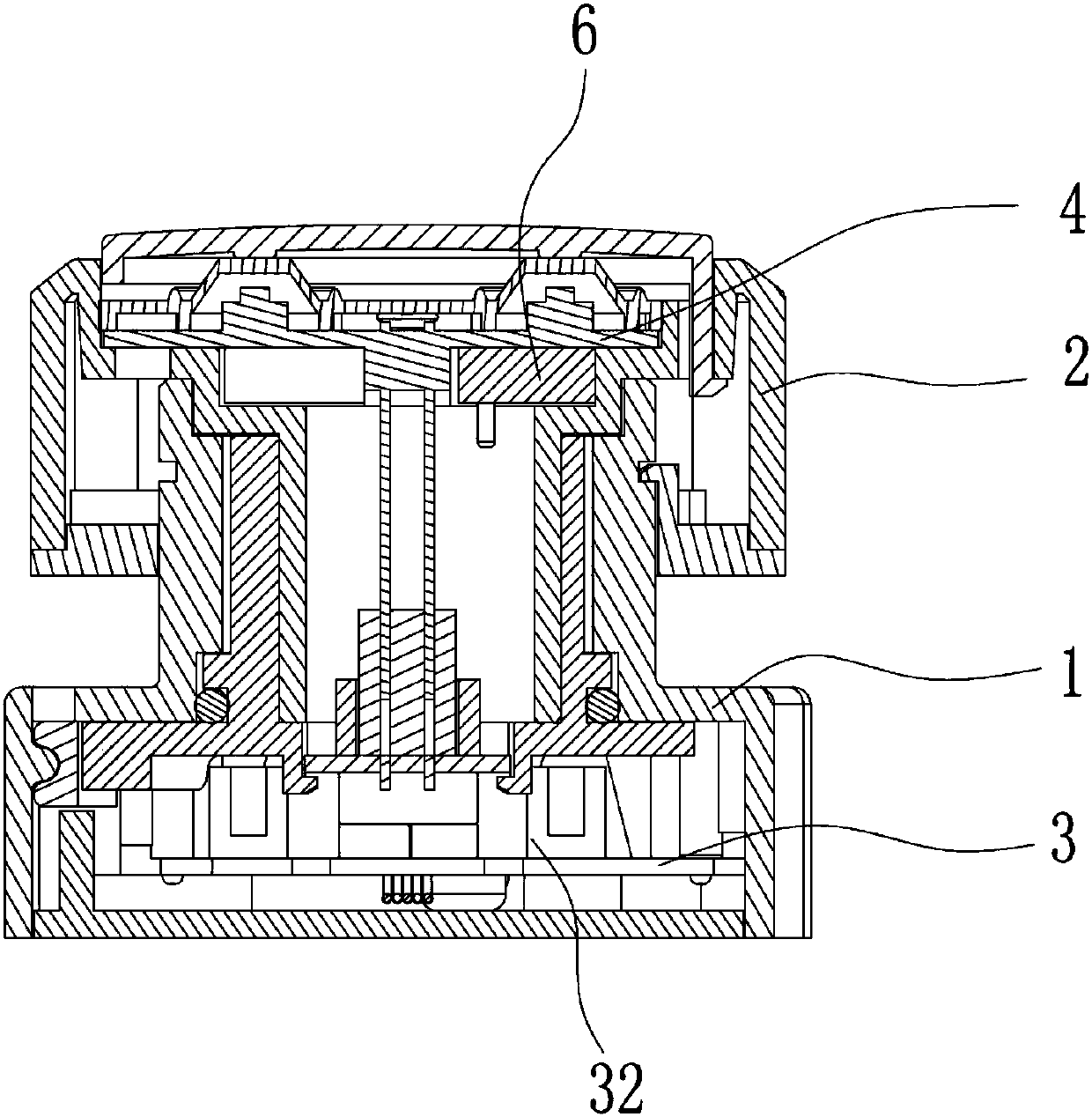
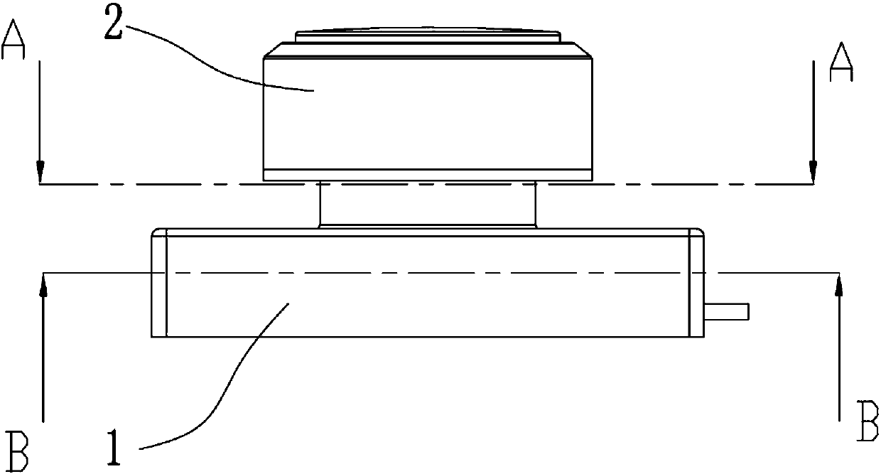
[0036] Such as figure 1 As shown, the present embodiment discloses an intelligent toilet knob that provides vibration operation feedback. Such as figure 1 As shown, this embodiment includes a knob module host 1 and a knob assembly 2, and the knob assembly 2 is installed on the knob module host 1 to realize rotation. A main circuit board 3 and a plurality of gratings 32 are arranged inside the knob module host 1 . A sub-circuit board 4 is arranged inside the knob assembly 2 , and the main circuit board 3 is connected to the sub-circuit board 4 . A vibrating assembly 6 is arranged on the sub-circuit board 4 or the main circuit board 3 . In this embodiment, the vibrating component 6 is arranged on the sub-circuit board 4 , and the vibrating component 6 can use vibration motors, air motors, vibrating electromagnets and other components capable of generating vibrations.
[0037] The working principle of this embodiment is that when the knob assembly 2 is rotated, the grating 32...
Embodiment 2
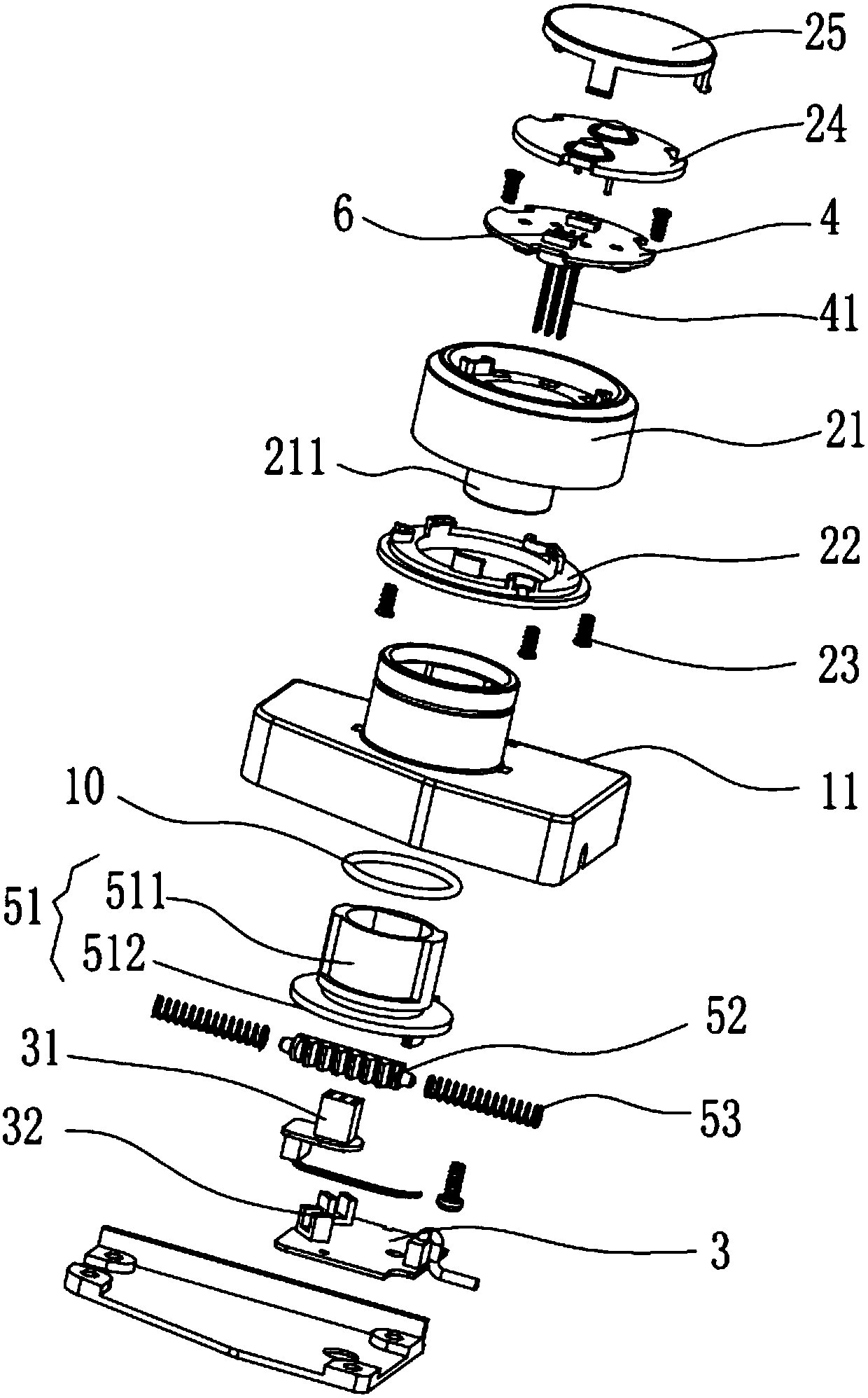
[0039] Such as Figure 2 to Figure 7 As shown, this embodiment discloses a smart toilet knob that provides vibration and light feedback. The smart toilet knob has the functions of easy disassembly and automatic reset through knob operation.
[0040] This embodiment includes a knob module host 1 and a knob assembly 2 . Such as Figure 6 As shown, the knob module host 1 is provided with a main circuit board 3 . The knob module host 1 includes a body shell 11 and a shaft assembly 5 disposed in the body shell 11 . The main circuit board 3 has a socket 31 and a plurality of gratings 32 . combine Figure 10 As shown, the shaft assembly 5 includes a shaft 51 , a rack 52 and two sets of pressure springs 53 . The inner wall of the body shell 11 is provided with two compression spring installation grooves 111 and a rack installation track 112 horizontally arranged in the middle of the two sets of compression spring installation grooves 111. The rack 52 is arranged on the rack instal...
Embodiment 3
[0049] Such as Figure 14 As shown, the difference between the present embodiment and the second embodiment is that: the sub-circuit board 4 or the main circuit board 3 is also provided with a speaker 9, and the light blocking information when the grating 32 senses the knob assembly 2 is fed back to the main circuit board. The circuit board 3 controls the loudspeaker 9 to sound in addition to controlling the vibration of the vibrating assembly 6 and the brightening of the LED lights 8 .
[0050] When the user operates the knob assembly, such as forward rotation, reverse rotation, pressing down, continuous forward rotation, and continuous reverse rotation; for different operations, the sound from the speaker 9 of the knob assembly 2 changes, the color of the light changes, and the vibration frequency changes. Variety. So that the user can directly feel the operation feedback.
PUM
 Abstract
Description
Claims
Application Information
 - R&D
- Intellectual Property
- Life Sciences
- Materials
- Tech Scout
- Unparalleled Data Quality
- Higher Quality Content
- 60% Fewer Hallucinations
Browse by: Latest US Patents, China's latest patents, Technical Efficacy Thesaurus, Application Domain, Technology Topic, Popular Technical Reports.
© 2025 PatSnap. All rights reserved.Legal|Privacy policy|Modern Slavery Act Transparency Statement|Sitemap|About US| Contact US: help@patsnap.com


