Supercharge Your Innovation With Domain-Expert AI Agents!

Air bearing module

An air bearing and air flotation technology, used in air cushion bearings, bearings, hydrostatic bearings, etc., can solve problems such as inability to dynamically adjust, difficult miniaturization of air bearing modules, and inability to maintain high rigidity of air film.

Inactive Publication Date: 2018-04-20
AU OPTRONICS CORP
View PDF3 Cites 3 Cited by
  • Summary
  • Abstract
  • Description
  • Claims
  • Application Information

AI Technical Summary

Problems solved by technology

[0003] At present, if the traditional air bearing module uses screws to adjust the air bearing gap between the guide rail and the slider, the size of the screw is limited, and the air bearing module is difficult to miniaturize, or cannot perform high-precision dynamic adjustment.
In addition, if the slider or guide rail has dimensional tolerances in different areas, the air bearing gap between the slider and the guide rail in different areas will fluctuate, making the air bearing gap between the guide rail and the slider The air film cannot maintain high rigidity

Method used


Image

  • Air bearing module
  • Air bearing module
  • Air bearing module

Examples


Embodiment Construction

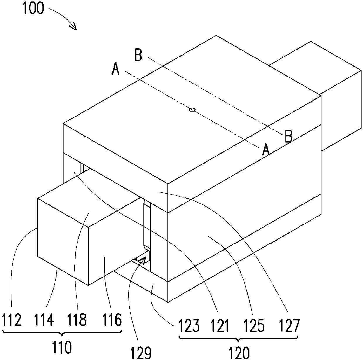
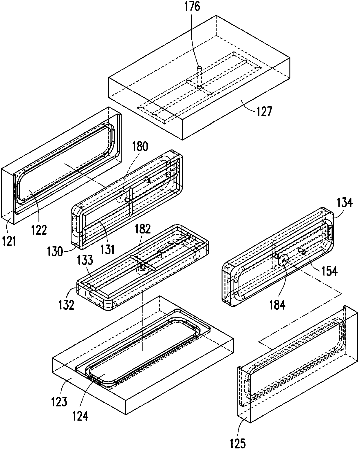
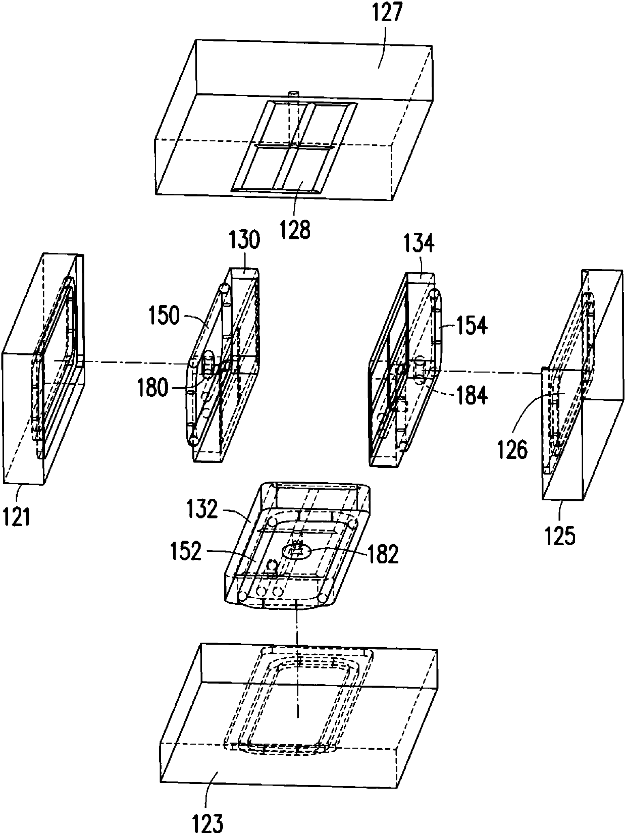
[0075] figure 1 is a schematic diagram of an air bearing module according to an embodiment of the present invention. figure 2 and image 3 respectively figure 1 Exploded schematic diagrams of different viewing angles behind the hidden guide rail of the air bearing module.

[0076] see Figure 1 to Figure 3 , the air bearing module 100 of this embodiment includes a guide rail 110, a slider 120, a first air bearing plate 130 (marked in figure 2 ), the second air floating plate 132 (marked on figure 2 ) and the third air floating plate 134 (marked on figure 2 ). The guide rail 110 has a first surface 112 , a second surface 114 , a third surface 116 and a fourth surface 118 . In this embodiment, the guide rail 110 is a cuboid as an example, and the first surface 112, the second surface 114, the third surface 116 and the fourth surface 118 of the guide rail 110 are respectively four consecutive surfaces, that is to say, The first surface 112 is adjacent to the second su...


PUM


Abstract

The invention disclsoes an air bearing module including a guide rail, a sliding block, a first air floating plate and a second air floating plate. The guide rail has a first surface and a second surface. The sliding block has a groove, a first inner wall and a second inner wall, the guide rail passes through the groove so that the sliding block can slide relative to the guide rail. The first air floating plate is located between the first surface and the first inner wall surface, wherein a first air cavity is formed between the first air floating plate and the first inner wall surface and a first air floating gap is formed between the first air floating plate and the first surface. The second air floating plate is located between the second surface and the second inner wall surface, wherein a second air cavity is formed between the second air floating plate and the second inner wall surface and a second air floating gap is formed between the second air floating plate and the second surface. The air bearing module allows dimensional micromation or high-precise dynamic adjustment.

Description

technical field [0001] The invention relates to an air bearing module, and in particular to an air bearing module that can be miniaturized, can be dynamically adjusted with high precision and has high rigidity. Background technique [0002] With the development of industrial technology, non-contact bearing modules have been practically applied in many fields. The non-contact bearing module takes the air bearing module as an example, which fills air between the guide rail and the slider, and forms an air film (air layer) between the guide rail and the slider. In this way, the guide rail and the slider will not be in direct contact during the sliding process, avoiding friction between the guide rail and the slider during sliding, and reducing the probability of component loss. [0003] At present, if the traditional air bearing module uses screws to adjust the air bearing gap between the guide rail and the slider, the size of the screw is limited, and the air bearing module i...

Claims


Application Information

Patent Timeline
Patent Type & Authority Applications(China)
IPC IPC(8): F16C32/06
CPCF16C32/0603F16C32/067
Inventor 刘荣井
Owner AU OPTRONICS CORP
Features
  • R&D
  • Intellectual Property
  • Life Sciences
  • Materials
  • Tech Scout
  • Unparalleled Data Quality
  • Higher Quality Content
  • 60% Fewer Hallucinations
Learn More