Yarn guide part for textile machines

A mechanical guiding and textile technology, which is applied in the direction of conveying filamentous materials, thin material processing, transportation and packaging, etc. It can solve the problem that the position of the guide ring cannot be changed at will, the structure of the guide part is not stable enough, and it cannot be clamped and dismantled at will, etc. problems, to save time and energy, easy to move, free clamping and dismantling effects

Inactive Publication Date: 2018-04-24
YANCHENG YANYI TECH CO LTD
View PDF0 Cites 7 Cited by
  • Summary
  • Abstract
  • Description
  • Claims
  • Application Information

AI Technical Summary

Problems solved by technology

The structure of the existing yarn guide parts is not stable enough, cannot be moved, can not be clipped and dismantled at will, and the position of the yarn guide ring cannot be changed at will

Method used


Image

  • Yarn guide part for textile machines
  • Yarn guide part for textile machines

Examples


Embodiment Construction

[0014] The following will clearly and completely describe the technical solutions in the embodiments of the present invention with reference to the accompanying drawings in the embodiments of the present invention. Obviously, the described embodiments are only some of the embodiments of the present invention, not all of them.

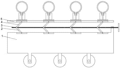
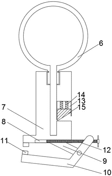
[0015] refer to Figure 1-2 , a yarn guiding part of a textile machine, comprising a base 1 and a yarn guiding ring 6, the base 1 is rotatably connected to a plurality of first connecting rods 2, and each first connecting rod 2 is rotatably connected to a second connecting rod 4 at one end away from the base 1 , each connecting part of the first connecting rod 2 and the second connecting rod 4 is provided with a threaded sleeve, the base 1 is provided with a first threaded rod 3, and the first threaded rod 3 runs through a threaded sleeve and extends, and the second connecting rod 4 One end away from the first connecting rod 2 is rotationally connected ...


PUM


Abstract

The invention discloses a yarn guide component of a textile machine, comprising a base and a yarn guide ring. The base is rotatably connected with a plurality of first connecting rods, and each of the first connecting rods is rotatably connected with a second connecting rod at one end away from the base. , each connecting part of the first connecting rod and the second connecting rod is provided with a threaded sleeve, the base is provided with a first threaded rod, and the first threaded rod penetrates and extends through all the threaded sleeves, and the second connecting rod One end of the rod away from the first connecting rod is rotatably connected to a bottom plate, a connecting frame is arranged under the yarn guide ring, a groove is arranged in the connecting frame, a spring is arranged in the groove, and one end of the spring is connected to the connecting frame, so One end of the spring away from the connecting frame is connected with a slider, the bottom end of the connecting frame is provided with a threaded groove, and a second threaded rod is rotatably connected in the threaded groove, and the bottom end of the connecting frame is provided with a fixing plate. The invention has stable structure, is easy to move, can be clamped and disassembled at will, and can adjust the orientation of the yarn guiding device, and is worth popularizing.

Description

technical field [0001] The invention relates to the comprehensive technical field of textile machinery, in particular to a yarn guide component of a textile machinery. Background technique [0002] With the development of human beings in the field of science and technology, new materials and new technologies are widely used, and textiles are widely used as an excellent material. In the weaving process, in order to avoid yarn disorder, it is necessary to use a yarn guide device to guide the yarn. The existing textile yarn guide device is provided with a square hole, and the yarn is transported to the corresponding yarn through the square hole on the yarn guide device. on the production equipment. The structure of the existing yarn guide parts is not stable enough, cannot be moved, can not be clamped and removed at will, and the position of the yarn guide ring cannot be changed at will. Contents of the invention [0003] The purpose of the present invention is to solve the...

Claims


Application Information

Patent Timeline
Patent Type & Authority Applications(China)
IPC IPC(8): B65H57/26B65H57/06
CPCB65H57/26B65H57/06B65H2701/31
Inventor 王华
Owner YANCHENG YANYI TECH CO LTD
Why Eureka
Try Eureka