Electric compressor

A technology of electric compressors and compression mechanisms, which is applied in the direction of machines/engines, liquid fuel engines, mechanical equipment, etc., can solve the problems of damage to the liquid reservoir, noise, abnormal vibration of the liquid reservoir, etc., and achieve the effect of reducing abnormal vibration

Inactive Publication Date: 2018-04-24
HITACHI JOHNSON CONTROLS AIR CONDITIONING INC
View PDF8 Cites 0 Cited by
  • Summary
  • Abstract
  • Description
  • Claims
  • Application Information

AI Technical Summary

Problems solved by technology

Therefore, the electric compressor sometimes generates abnormal vibration and noise in the accumulator
In addition, depending on the situation, the electric compressor may cause resonance between the outer shell of the accumulator (container body) and the suction pipe, which may damage the accumulator.

Method used


Image

  • Electric compressor
  • Electric compressor
  • Electric compressor

Examples


Embodiment approach

[0031] The present invention also intends to solve the following problems.

[0032] (1) Generally, the electric compressor is expected to reduce abnormal vibration and noise generated in the accumulator. However, since there are many causes of abnormal vibration and noise, it is difficult to efficiently reduce the abnormal vibration and noise generated in the accumulator.

[0033] (2) The accumulator has a dual structure of an outer shell (container body) and a suction pipe arranged inside it in terms of its function and properties. In addition, the sources of vibration that vibrate the outer shell of the accumulator (container body) and the suction pipe inside are located at two places, the motor mechanism unit and the compression mechanism unit built in the airtight container. Furthermore, the frequency band of the vibration component generated in the motor mechanism part is different from the frequency band of the vibration component generated in the compression mechanism ...

Embodiment approach 1

[0037]

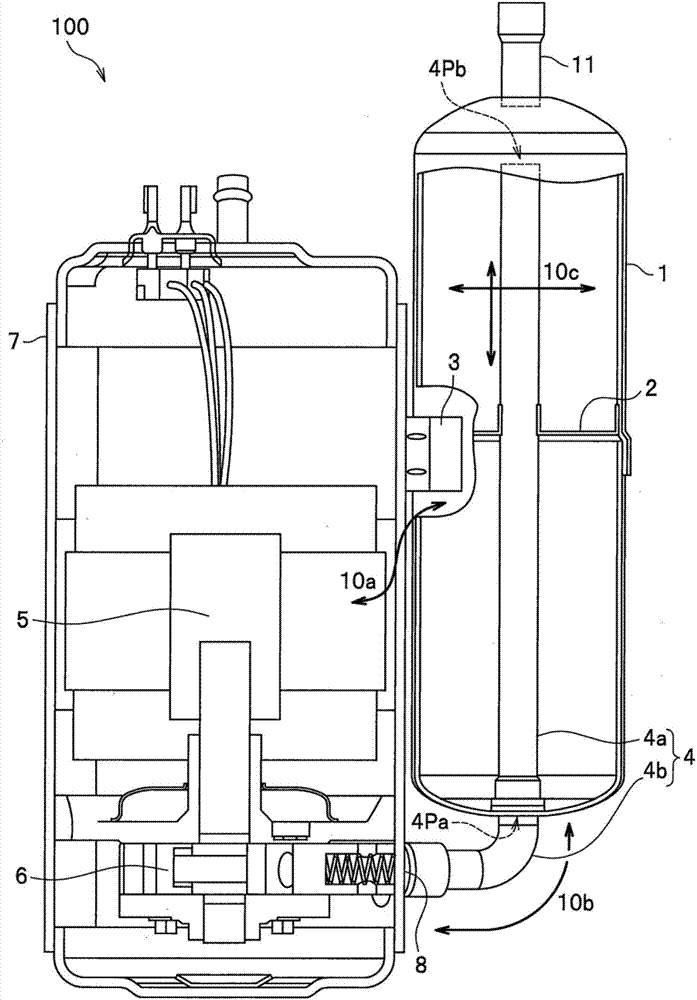
[0038] Below, refer to Figure 1 to Figure 3 , the configuration of electric compressor 100 according to Embodiment 1 will be described. Here, the electric compressor 100 will be described assuming that it is configured as a hermetic vertical rotary compressor. However, the electric compressor 100 may have a structure other than a hermetic vertical rotary compressor.

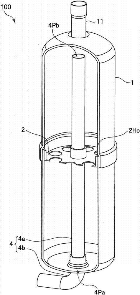
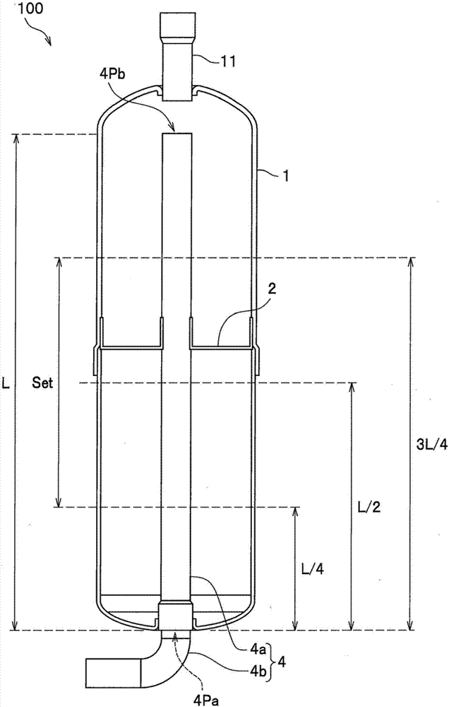
[0039] figure 1 It is a cross-sectional view showing the structure of electric compressor 100 according to Embodiment 1. figure 2 and image 3 Each is a cross-sectional view showing the structure of the accumulator 1 used in the electric compressor 100 . figure 2 The cross-sectional structure of the accumulator 1 viewed obliquely from above is shown. image 3 The cross-sectional structure of the accumulator 1 seen from the front direction is shown.

[0040] Such as figure 1 As shown, the electric compressor 100 according to Embodiment 1 includes a compression mechanism unit 6 for compressing ...

Embodiment approach 2

[0078] Below, refer to Image 6 and Figure 7 , the configuration of electric compressor 100A according to Embodiment 2 will be described. Image 6 It is a sectional view showing the structure of an electric compressor 100A according to the second embodiment. Figure 7 It is a sectional view showing the structure of the accumulator 1A used in the electric compressor 100A.

[0079] Such as Image 6 and Figure 7 As shown, it is the same as the electric compressor 100 of Embodiment 1 (refer to figure 1 and figure 2 ) compared with the electric compressor 100A of Embodiment 2 in that it has an accumulator 1A instead of the accumulator 1 . The accumulator 1A is an accumulator in which a supporting member 2 and a shielding member 9 are arranged inside. The shielding member 9 prevents liquid refrigerant (liquid refrigerant) from entering the suction pipe 4 . The liquid refrigerant is supplied to the accumulator 1A from a refrigeration cycle (not shown) through a supply pipe...


PUM


Abstract

The invention provides an electric compressor which can effectively reduce vibration of a suction tube. The electric compressor is provided with a compressing mechanism part (6) for compressing a refrigerant, an electric mechanism part (5) for driving the compressing mechanism part, an enclosed container (7) where the compressing mechanism part and the electric mechanism part are arranged, a liquid storage device (1) for temporarily storing the refrigerant, a suction tube (4) which supplies the refrigerant from the to a suction inlet (8) of the compressing mechanism part arranged in the enclosed container, and a support part (2) which supports the suction tube in the liquid storage device. A straight part of the suction tube is arranged in the liquid storage device in a manner of extendingin the up-down direction. With respect to the overall length L of the straight part of the suction tube, the support part is arranged on the position away from the connecting side end (4Pa) of the enclosed container and the suction tube for more than L / 4 and less than 3L / 4.

Description

technical field [0001] The invention relates to an electric compressor used in refrigerating equipment such as air conditioners and refrigerators. Background technique [0002] Electric compressors are used in refrigerating equipment such as air conditioners and refrigerators, for example. The electric compressor has a compression mechanism unit that compresses the refrigerant, an electric mechanism unit that drives the compression mechanism unit, an airtight container housing them, and an accumulator that temporarily stores the refrigerant. The airtight container and reservoir are secured by metal parts. In addition, the airtight container and the reservoir are connected by a connecting tube called a "suction tube". The electric compressor supplies the refrigerant from the accumulator to the suction port of the compression mechanism built in the airtight container through the suction pipe. [0003] In this configuration, in the electric compressor, vibration components o...

Claims


Application Information

Patent Timeline
IPC IPC(8): F04C23/02F04C29/12F04C29/06
CPCF04C23/02F04C29/06F04C29/12F04C2240/806
Inventor 黑野亮竹泽谦治土屋直洋
Owner HITACHI JOHNSON CONTROLS AIR CONDITIONING INC
Why Eureka
Try Eureka