
Multifunctional pilot maneuvering foot valve mechanism and using method thereof

A technology of operating valves and foot valves, which is applied to earth movers/excavators, construction, etc. It can solve the problems of inconvenient manufacture, use, and later maintenance, difficult layout, and many control pipelines, etc., to achieve optional lifting High performance, easy operation and high reliability

Active Publication Date: 2018-04-27
XCMG EXCAVATOR MACHINERY
View PDF5 Cites 2 Cited by
  • Summary
  • Abstract
  • Description
  • Claims
  • Application Information

AI Technical Summary

Problems solved by technology

[0002] Construction machinery, especially excavators, often add various tools to meet the needs of different working conditions. Various tools require different operating methods. The traditional method is to Each machine tool corresponds to one operation switch, but the space inside the cab of construction machinery is already very compact, the layout is relatively difficult, and there are many control pipelines. In addition, the driver needs to understand the corresponding function of each switch first, and the adjacent switches are still connected. It is easy to cause accidents due to misoperation, so it is inconvenient to manufacture, use or maintain later

Method used


Image

  • Multifunctional pilot maneuvering foot valve mechanism and using method thereof
  • Multifunctional pilot maneuvering foot valve mechanism and using method thereof
  • Multifunctional pilot maneuvering foot valve mechanism and using method thereof

Examples


Embodiment Construction

[0026] The present invention will be further described below in conjunction with specific embodiments.

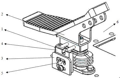
[0027] Such as Figure 1-7 As shown, a multifunctional pilot operated foot valve mechanism includes a two-way pilot operated valve 1, a foot pedal 2, a fixed bracket 3, a sliding bracket 4 and a lock pin 5. The two-way pilot operated valve 1 is assembled on the large floor 6 of the cab The upper part is generally located at the position where the driver’s right foot is placed. The foot pedal 2 is assembled on the two-way pilot foot valve 1. The driver can step on the foot pedal 2 back and forth with his feet.

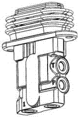
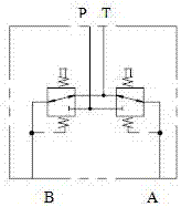
[0028] figure 2 It is a schematic diagram of the structure of the two-way pilot control valve. The front and rear ends of the two-way pilot control valve 1 are provided with mounting holes. The two-way pilot control valve 1 is assembled on the large floor 6 of the cab through the bolts passing through the mounting holes. The two-way pilot control valve 1 There are two t...


PUM


Abstract

The invention discloses a multifunctional pilot maneuvering foot valve mechanism and a using method thereof. The mechanism comprises a double-direction pilot maneuvering valve, a foot plate, a fixingsupport, a sliding support and a locking pin. The double-direction pilot maneuvering valve is assembled on a large bottom plate of a cab. The foot plate is assembled on the double-direction pilot maneuvering valve. An E-shaped sliding groove is formed above the fixing support and opened downwards, and a line-shaped sliding groove is formed below the E-shaped sliding groove. The sliding support isinstalled between the double-direction pilot maneuvering valve and the fixing support. An eccentric groove is formed in the top of the sliding support, a vertical blind hole sliding groove is formed in the middle, and a thread hole is formed in the bottom. The locking pin is in a T shape, a sliding block is arranged at one end of the large head, and a long round rod is arranged at the other end. According to the multifunctional pilot maneuvering foot valve mechanism and the using method thereof, the structure is simple, the cost is low, the operation is convenient, reliability is high, by adjusting the position of the locking pin, the functions of fixing the foot plate, controlling opening and closing in a one-way manner and in a two-way manner and the like are achieved, operation mannersof multiple addition machine tools are achieved, the selectivity of the addition machine tools is improved, and fast switching of the operation manners is improved.

Description

Technical field [0001] The invention belongs to the technical field of engineering machinery, and specifically relates to a multifunctional pilot operated foot valve mechanism and a method of use thereof. Background technique [0002] Construction machinery, especially excavators, often add various tools to meet the needs of different working conditions. Various tools require different operation methods. The traditional method is that each tool corresponds to an operation switch, but the cab space of construction machinery is originally It is already very compact, the layout is more difficult, and there are many control pipelines. In the later stage, the driver needs to understand the corresponding function of each switch, and the adjacent switches are also prone to accidents due to misoperation, so whether it is manufacturing, use or later Maintenance is not convenient. Summary of the invention [0003] The purpose of the present invention is to provide a multifunctional pilot o...

Claims


Application Information

Patent Timeline
IPC IPC(8): E02F9/20E02F9/22
CPCE02F9/2004E02F9/2267
Inventor 李会超张升霞张聪聪姜毅初金涛石晓妹杨晓磊王春磊宗波马鑫王绪通
Owner XCMG EXCAVATOR MACHINERY
Learn More