
Anti-pulling device for lock

A technology of anti-dialing and locks, which is applied in the field of locks, can solve problems such as complex linkage structures, disadvantages, and inability to meet needs, and achieve the effect of increasing modern technology, reducing complexity, and improving reliability

Active Publication Date: 2018-04-27
DANGTU COUNTY KEHUI TRADING
View PDF4 Cites 2 Cited by
  • Summary
  • Abstract
  • Description
  • Claims
  • Application Information

AI Technical Summary

Problems solved by technology

[0003] The purpose of the present invention is to solve the shortcomings in the prior art, such as: the traditional anti-dialing device of the lock has a very complicated linkage structure, which greatly increases the complexity of the lock, which will be unfavorable to both production and use. Influenced by the influence, and the traditional anti-dialing device lacks technological content and cannot meet the needs of modern life, a kind of anti-dialing device for locks is proposed

Method used

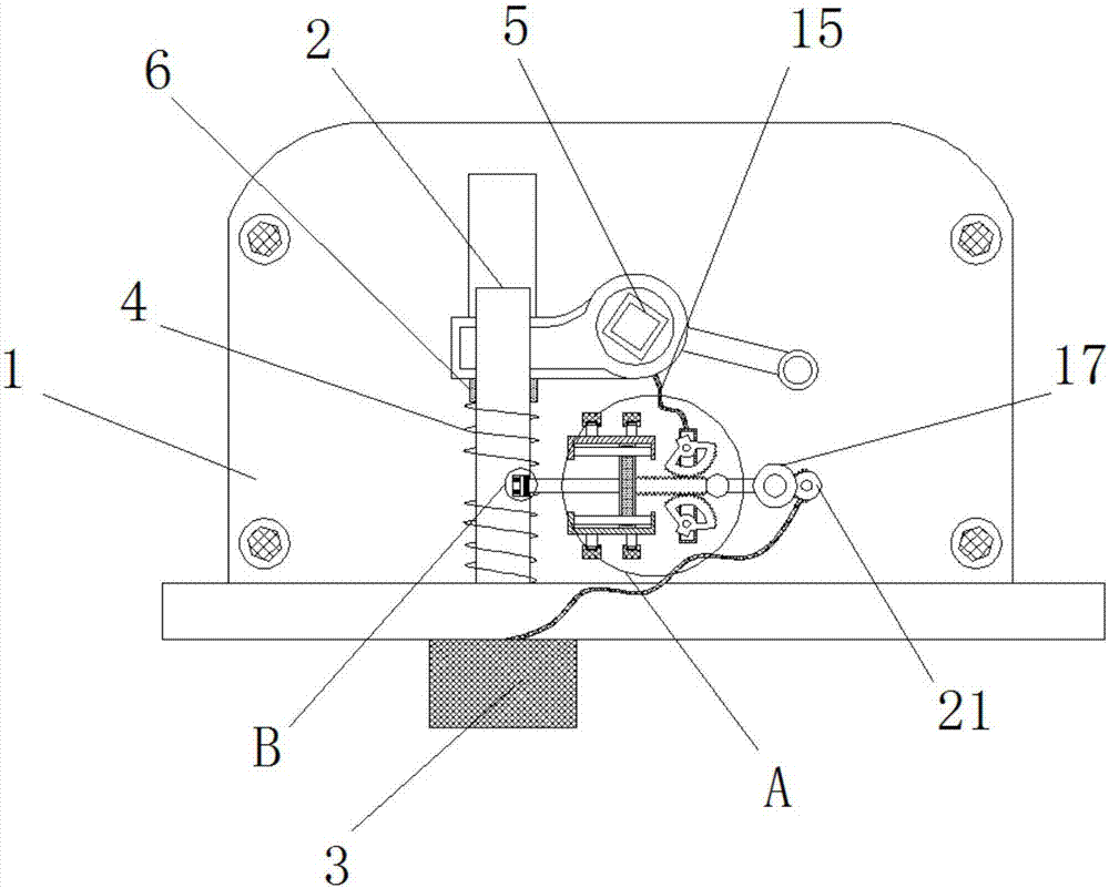
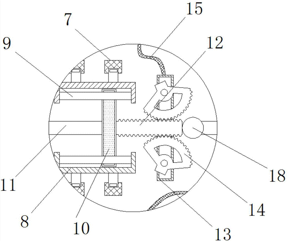
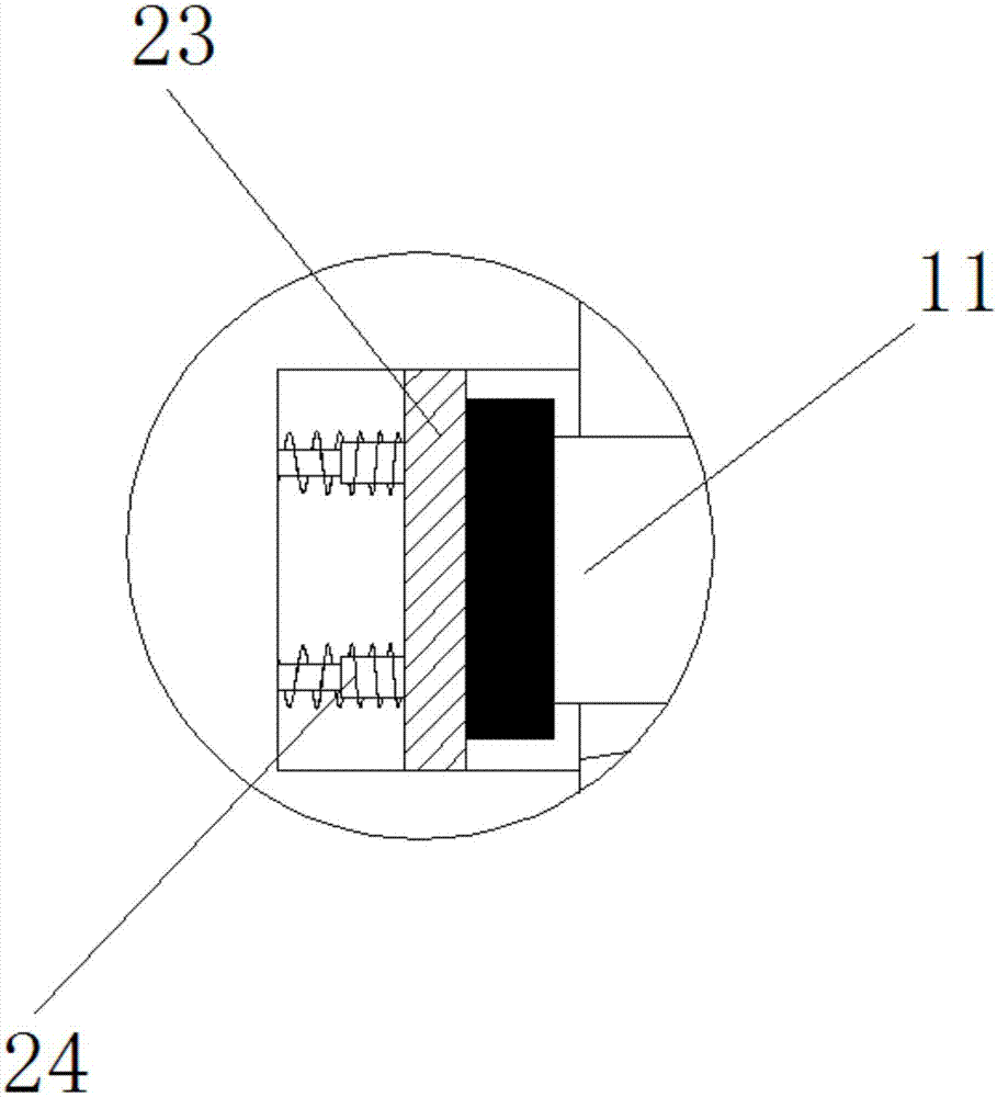

Image

  • Anti-pulling device for lock
  • Anti-pulling device for lock
  • Anti-pulling device for lock

Examples


Embodiment Construction

[0018] The following will clearly and completely describe the technical solutions in the embodiments of the present invention with reference to the accompanying drawings in the embodiments of the present invention. Obviously, the described embodiments are only some, not all, embodiments of the present invention.

[0019] In describing the present invention, it should be understood that the terms "upper", "lower", "front", "rear", "left", "right", "top", "bottom", "inner", " The orientation or positional relationship indicated by "outside", etc. is based on the orientation or positional relationship shown in the drawings, and is only for the convenience of describing the present invention and simplifying the description, rather than indicating or implying that the referred device or element must have a specific orientation, so as to Specific orientation configurations and operations, therefore, are not to be construed as limitations on the invention.

[0020] refer to Figure ...


PUM


Abstract

The invention discloses an anti-pulling device for a lock. The anti-pulling device comprises a lock shell, a key hole connecting piece is arranged in the lock shell, a sliding hole is formed in one end of the key hole connecting piece, a first transmission rod in sliding connection with the sliding hole is inserted into the sliding hole, the first transmission rod is sleeved with a limiting ring fixedly connected with the first transmission rod, the limiting ring is located on one side of the key hole connecting piece, a groove is formed in the lower side of the lock shell, a spring bolt in sliding connection with the groove is inserted into the groove, one end of the first transmission rod penetrates the groove in the lock shell and is fixedly connected with one end of the spring bolt. The anti-pulling device has the beneficial effects that a traditional anti-pulling device for the lock is improved, a power source is controlled to be started or stopped through contact between the keyand the spring bolt and a lock groove, the transmission device is controlled to move, motion of the anti-pulling device is controlled further, the complex degree of the traditional anti-pulling devicefor the lock is reduced, meanwhile, modern science and technology are increased, the lock reliability is greatly improved, and the needs of modern life are better met.

Description

technical field [0001] The invention relates to the technical field of locks, in particular to an anti-dialing device of a lock. Background technique [0002] A lockset refers to a device that acts as a seal, including locks, keys and accessories. It is generally interpreted as "a seal that must be opened with a key." Now, in addition to being opened with a key, the lock can also be opened with light, electricity, Instructions such as magnetic, acoustic and fingerprint are turned on. Locks are not only protective equipment, but also have the functions of "management" and "decoration". There is also a kind of etiquette in international communication, which is to express friendship by giving a symbolic "key". With the improvement of people's living standards and the strengthening of people's awareness of prevention, the demand for high-end preventive locks continues to increase. Most of the locks are equipped with an anti-dialing device to prevent the lock from being opened...

Claims


Application Information

Patent Timeline
Patent Type & Authority Applications(China)
IPC IPC(8): E05B47/00E05B15/14
Inventor 秦雪芳
Owner DANGTU COUNTY KEHUI TRADING
Learn More