Method for measuring air flow of turbine blade machined holes

A technology of turbine blades and air flow, applied in the direction of liquid/fluid solid measurement, measurement device, measurement capacity, etc., can solve the problem of not accurately reflecting the flow state of the back cavity machine plus the exhaust hole 24, so as to ensure the accuracy of measurement, The effect of avoiding errors

Active Publication Date: 2018-04-27
CHINA HANGFA SOUTH IND CO LTD
View PDF8 Cites 16 Cited by
  • Summary
  • Abstract
  • Description
  • Claims
  • Application Information

AI Technical Summary

Benefits of technology

This patented technology allows us to accurately determine how well two parts are doing together when they work properly without any mistakes from converting them into another form or adding extra components like holes on their surface.

Problems solved by technology

This technical problem addressed in this patents relates to improving the efficiency and durability of aerospace engines' (a type of aircraft) aerodynamic vane used during flight operations such as takeoff or landing. To improve these properties, certain materials like ceramic fiber reinforced plastic ("CFRP") may be added into the interior space between two layers called chambers. These components help distribute the loadings evenly throughout the entirety of the component while maintaining sufficient coolant flows within specific areas. However, current techniques require multiple steps before reaching steady conditions, leading to increased time delays and decreased reliability.

Method used


Image

  • Method for measuring air flow of turbine blade machined holes
  • Method for measuring air flow of turbine blade machined holes
  • Method for measuring air flow of turbine blade machined holes

Examples


Embodiment Construction

[0026] In order to have a clearer understanding of the technical features, purposes and effects of the present invention, the specific implementation manners of the present invention will now be described with reference to the accompanying drawings. Wherein, the same parts adopt the same reference numerals.

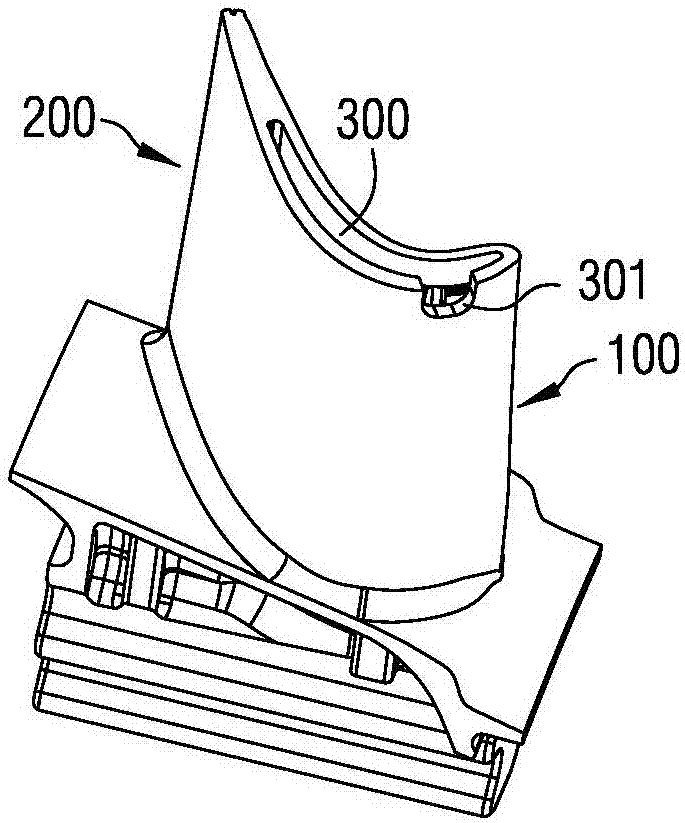
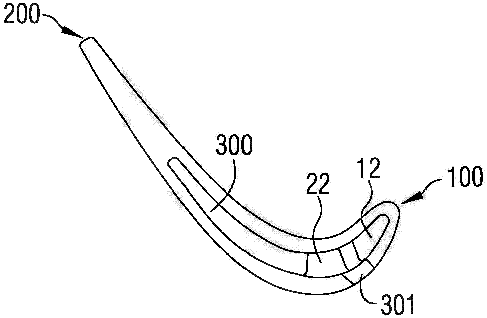
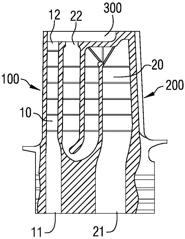
[0027] figure 1 It is a schematic diagram of a three-dimensional structure of an aeroengine gas turbine blade; figure 2 for figure 1 Schematic diagram of the structure principle of the blade tip; image 3 for figure 1 Schematic diagram of the cross-sectional structure of the casting blank of the blade; Figure 4 for figure 1 Schematic diagram of the cross-sectional structure of the blade; Figure 5 It is a schematic diagram of the three-dimensional structure principle of the biconical yellow wax prepared by a method for measuring the air flow rate of a turbine blade machine with holes added according to a specific embodiment of the present invention; Figure 6 for...


PUM


Abstract

The invention relates to a method for measuring air flow of turbine blade machined holes. The method comprises the following steps: step A, square yellow wax with side length of 10 mm or more is pressed into a double cone shape, and the distance between two cone tips is from 3 mm to 6 mm; step B, the double cone-shaped yellow wax produced in step A is pressed into a blade tip slot, so that the blade tip slot is filled with the yellow wax; step C, plugged turbine blades in step B are placed in a thermostat while maintaining blade tips upwards, the temperature of the thermostat is adjusted to 50DEG C, and the plugged turbine blades are taken out after being heated for 30 seconds to 60 seconds and then placed in a constant temperature of 20 DEG C for about 20 minutes, so that the yellow waxis completely cooled and solidified; step D, flow measurement is performed; step E, the yellow wax in the turbine blades is removed to complete the measurement. The method can be used for directly measuring flow data of a back cavity machined vent hole, thereby effectively ensuring measurement accuracy.

Description


Claims


Application Information

Patent Timeline
Owner CHINA HANGFA SOUTH IND CO LTD
Why Eureka
Try Eureka