Inter-domain TE-LSP selection

a traffic engineering and inter-domain technology, applied in the field of computer networks, can solve the problems of path computation at the head-end lsr, inter-domain te-lsps, and burdensome management of interconnected computer networks, so as to avoid some of the risks and possible errors

Inactive Publication Date: 2006-06-08
CISCO TECH INC
View PDF18 Cites 55 Cited by
  • Summary
  • Abstract
  • Description
  • Claims
  • Application Information

AI Technical Summary

Benefits of technology

[0018] Advantageously, the novel technique enables efficient selection of a TE-LSP (or multiple TE-LSPs for load balancing) from among a plurality of TE-LSPs that span multiple domains in order to reach an address prefix in a domain that is remote from the head-end node domain. By providing a dynamically selectable technique, the invention provides an alternative to sub-optimal selection techniques, such as cumbersome manual configuration (e.g., static routing or policy routing), that can avoid some of the risks and possible errors created in such sub-optimal selection techniques.

Problems solved by technology

Since management of interconnected computer networks can prove burdensome, smaller groups of computer networks may be maintained as routing domains or autonomous systems.
One difficulty that arises in crossing domain boundaries is that path computation at the head-end LSR requires knowledge of network topology and resources across the entire network between the head-end and the tail-end LSRs.
Yet service providers typically do not share this information with each other across domain borders.
A known limitation of multiple inter-domain TE-LSPs lies in the inability to efficiently select (e.g., at a headend node in the local domain) which particular TE-LSP to use when attempting to reach a particular reachable prefix (e.g., in the remote domain), should there be a plurality of TE-LSPs available to reach a particular prefix.
Current methods to select a particular TE-LSP involve the use of static or policy-based routing (manual configuration), which can be cumbersome and limited in their applicability, and in some cases (e.g., misconfiguration) can be the cause of network failure.

Method used


Image

  • Inter-domain TE-LSP selection
  • Inter-domain TE-LSP selection
  • Inter-domain TE-LSP selection

Examples


Embodiment Construction

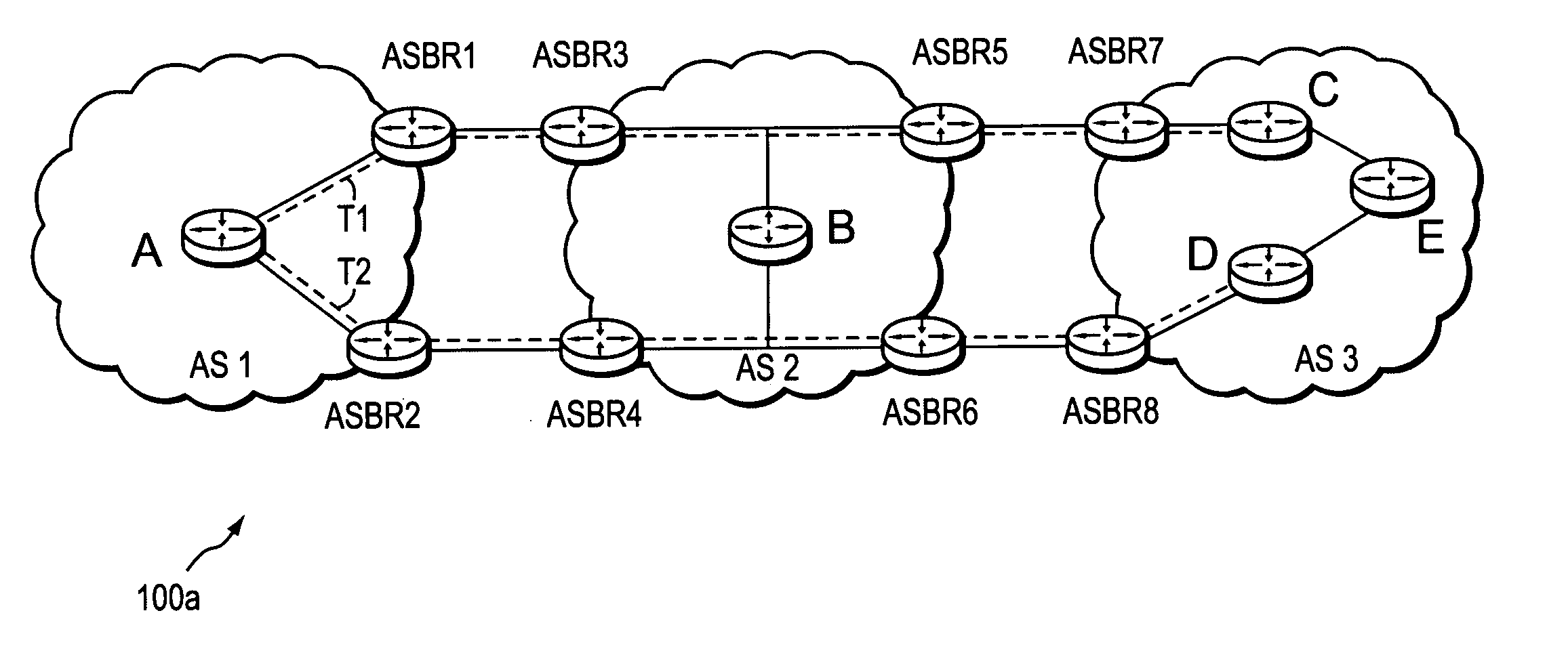
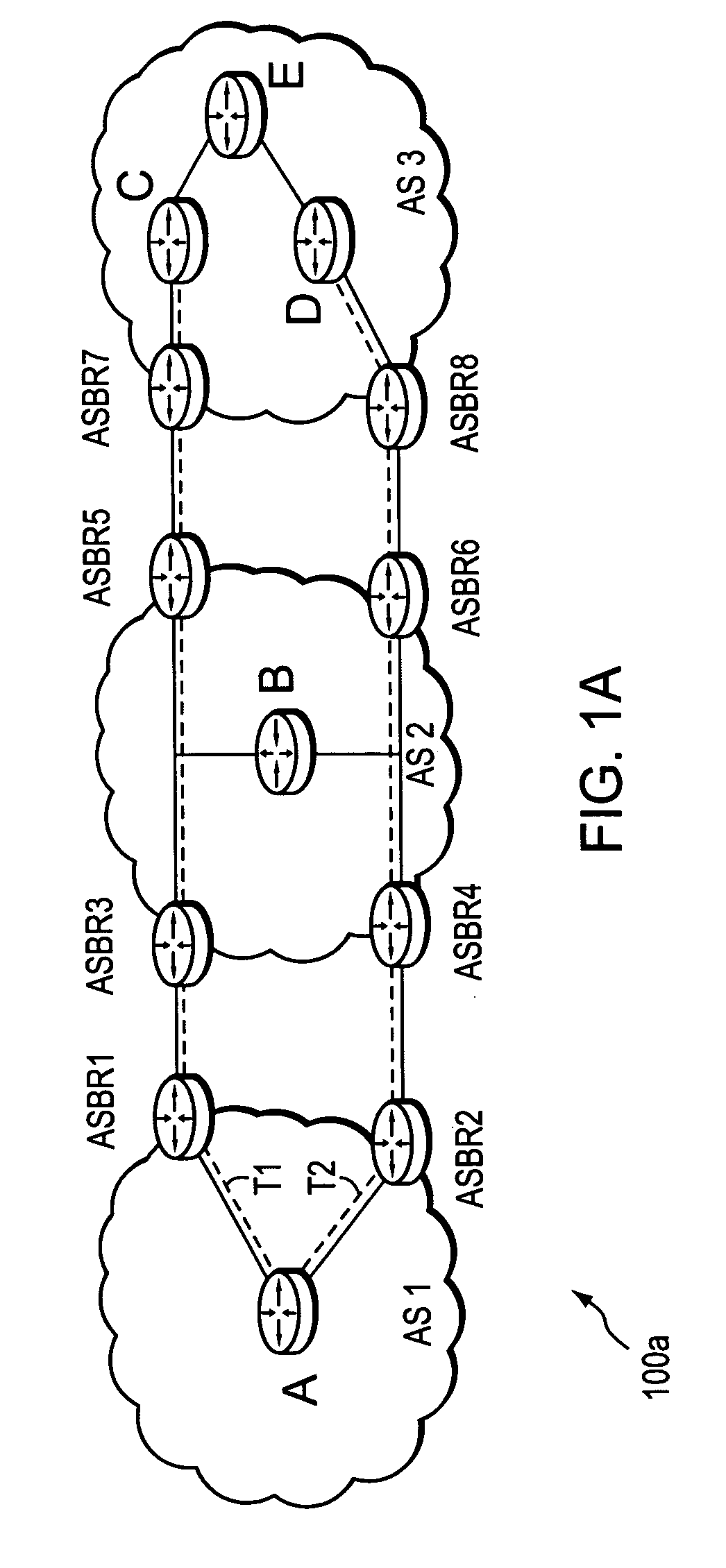
[0025]FIG. 1A is a schematic block diagram of an exemplary computer network 100a comprising autonomous systems AS1 and AS3 interconnected by autonomous system AS2. An Autonomous System (AS) is herein defined to be a group of intermediate nodes, such as intradomain routers, within a network that are subject to a common authority and execute one or more intradomain routing protocols. Although each AS is illustratively an autonomous system, those skilled in the art will appreciate that the ASes may alternatively be configured as routing domains or other networks or subnetworks. The autonomous system AS1 includes intradomain routers, such as AS border routers ASBR1 and ASBR2, through which communication, such as data packets, may pass into and out of the AS to AS border routers ASBR3 and ASBR4, respectively of AS2. AS2 also includes AS border routers ASBR5 and ASBR6 in communication with border routers ASBR7 and ASBR8 of AS3. Moreover, within AS1 and AS2, there are exemplary intradomain...


PUM


Abstract

A technique selects a traffic engineering (TE) label switched path (LSP) from among a plurality of TE-LSPs, each of which spans multiple domains of a computer network from a head-end node of a local domain to a tail-end node of a remote domain, in order to reach one or more address prefixes within the remote domain. The inter-domain TE-LSP selection technique comprises a selection algorithm executed by the head-end node and based on predetermined TE-LSP attributes (e.g., bandwidth, cost, etc.) and / or address prefix reachability attributes (e.g., cost from a tail-end node to the prefix) to select an appropriate inter-domain TE-LSP for the reachable address prefix. The selection algorithm is embodied in one of two modes: (i) a hierarchical selection mode, or (ii) a weighted selection mode. In addition, the technique comprises a load balancing aspect that cooperates with the selection algorithm to enable the head-end node to balance traffic loads among the multiple TE-LSPs based on the results of the selection algorithm.

Description

RELATED APPLICATIONS [0001] This application is related to U.S. application Ser. No. (Atty. Docket No. 112025-0600), entitled PROPAGATION OF ROUTING INFORMATION IN RSVP-TE FOR INTER-DOMAIN TE-LSPS, and U.S. application Ser. No. (Atty. Docket No. 112025-0601), entitled INTER-DOMAIN TE-LSP WITH IGP EXTENSIONS, both filed by Vasseur et al. on Dec. 1, 2004, the contents of both which are hereby incorporated in their entirety. BACKGROUND OF THE INVENTION [0002] 1. Field of the Invention [0003] The present invention relates to computer networks and more particularly to selecting a traffic engineering (TE) label switched path (LSP) from a plurality of TE-LSPs that span multiple domains of a computer network. [0004] 2. Background Information [0005] A computer network is a geographically distributed collection of nodes interconnected by communication links and segments for transporting data between end nodes, such as personal computers and workstations. Many types of networks are available, ...

Claims


Application Information

Patent Timeline
Patent Type & Authority Applications(United States)
IPC IPC(8): H04J1/16H04L12/56
CPCH04L45/04H04L45/24H04L45/50H04L47/10H04L47/125
Inventor VASSEUR, JEAN-PHILIPPEPREVIDI, STEFANO B.
Owner CISCO TECH INC
Why Eureka
Try Eureka