Tool setting device and method for micro lathe

A tool setting device, a tiny technology, applied in auxiliary devices, turning equipment, tool holder accessories, etc., can solve the problems of determining the adjustment amount of the tool, inconsistent cutting amount, difficulty in ensuring the shape accuracy of small workpieces, etc., to improve stability, Realize the effect of real-time measurement

Active Publication Date: 2012-10-03
CHANGCHUN UNIV OF SCI & TECH
View PDF4 Cites 52 Cited by
  • Summary
  • Abstract
  • Description
  • Claims
  • Application Information

AI Technical Summary

Problems solved by technology

In the process of high-precision machining, there are the following problems: First, it is difficult to determine the adjustment amount of the tool by visually observing whether the end face after turning is flat or

Method used


Image

  • Tool setting device and method for micro lathe
  • Tool setting device and method for micro lathe
  • Tool setting device and method for micro lathe

Examples


Embodiment Construction

[0017] The present invention will be described in further detail below in conjunction with the accompanying drawings and embodiments.

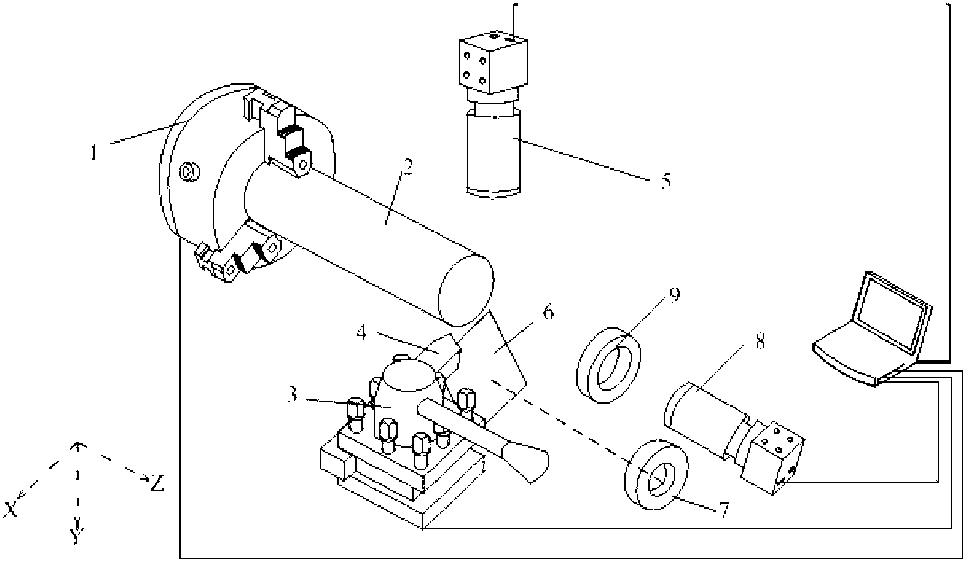
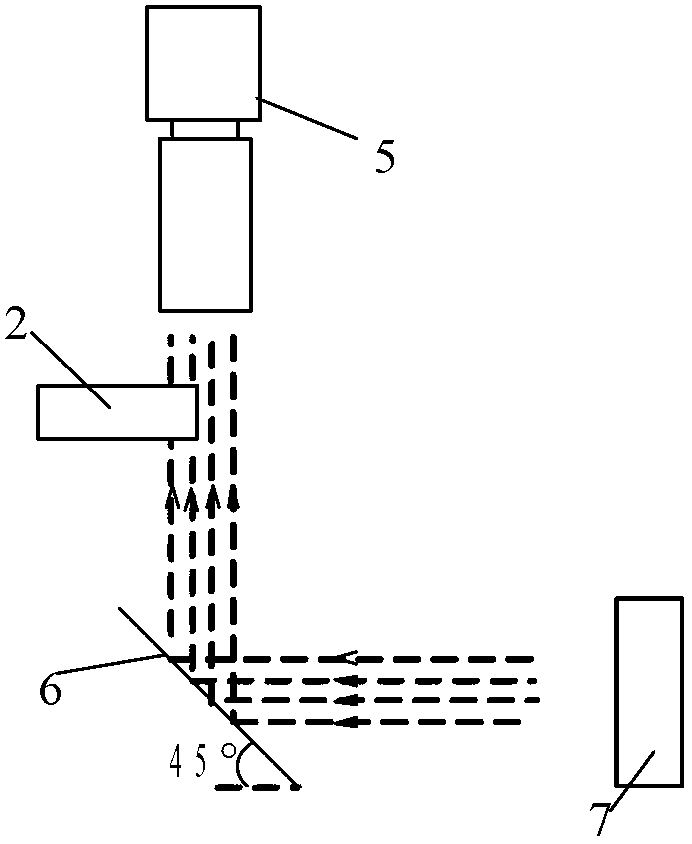
[0018] Such as figure 1 As shown, the tool setting device for a micro lathe includes: a machine chuck 1, a tool holder 3, a tool 4 and a guide rail, and the device also includes: a first CCD camera 5, a mirror 6, a first light source 7, and a second CCD Camera 8, second light source 9 and external computer; in the lathe, the direction parallel to the main axis of the workpiece 2 is the Z axis, the horizontal radial direction of the workpiece is the X axis, and the direction where the tool is away from the workpiece is the positive direction. According to the right-hand rule, the direction perpendicular to the X-axis and perpendicular to the Z-axis is the Y direction. The workpiece 2 to be processed is clamped on the machine tool chuck 1, and the tool 4 is fixed on the tool holder 3; the external computer controls the machine tool chuck 1 and ...


PUM


Abstract

The invention discloses a tool setting device and a tool setting method for a micro lathe and belongs the technical field of mechanical automation. The device comprises a machine tool clamp plate, a tool rest, a tool, a guide rail, a first charge coupled device (CCD), a reflector, a first light source, a second CCD, a second light source and an outer computer. The method comprises the following steps of: calibrating pixels in the horizontal direction and pixels in the vertical direction respectively, and transmitting images containing actual distance information to the outer computer; monitoring and adjusting the tool to ensure that the tool approaches an end surface of a workpiece; displaying the distance between a tool nose and the rotary center of the end surface of the workpiece by a technology and software; manually adjusting the distance between the workpiece and the tool according to the obtained distances in the three directions, or controlling the relative motion of the tool and the workpiece by outputting corresponding signals through the computer so as to realize high-precision tool setting of the micro lathe. According to the device and the method, an image measurement technology is adopted, so that tool setting gaps can be automatically detected and can be measured in real time; and therefore, the tool setting difficulty is reduced, and the machining process can be well monitored.

Description

technical field [0001] The invention belongs to the technical field of mechanical automation, and in particular relates to a tool setting device and method for a micro lathe. Background technique [0002] In the process of high-precision machining, the accuracy of tool setting directly affects the surface machining accuracy of the workpiece. As the size of the workpiece to be processed is getting smaller and smaller, the tool setting accuracy of the lathe is getting higher and higher. The processing methods commonly used in the prior art mainly include ordinary lathes and CNC lathes, and the tool setting methods commonly used in these two methods There are trial cutting method and automatic tool setting instrument for tool setting. In the process of high-precision machining, if the traditional trial cutting method is used, whether it is tool setting in the X direction or Z direction, the workpiece will undergo plastic deformation after the test run, and the greater the amou...

Claims


Application Information

Patent Timeline
IPC IPC(8): B23B25/06
Inventor 于化东于占江许金凯张留新李晓舟李一全丁戗王晓冶
Owner CHANGCHUN UNIV OF SCI & TECH
Why Eureka
Try Eureka