
Stereoscopic projection light polarization modulation device and method, and stereoscopic image projection system

A polarization modulation and projection light technology, applied in the field of projection display, can solve the problems of large volume and small volume, and achieve the effect of reducing the volume and reducing the optical path difference.

Pending Publication Date: 2018-05-01
SHENZHEN TIME WAYING TECH
View PDF0 Cites 2 Cited by
  • Summary
  • Abstract
  • Description
  • Claims
  • Application Information

AI Technical Summary

Problems solved by technology

[0007] The technical problem to be solved by the embodiments of the present invention is the large volume of the existing stereoscopic projection polarization modulation device based on the dual optical path polarization splitting technology, and aims to provide a new and smaller stereoscopic projection polarization modulation device

Method used


Image

  • Stereoscopic projection light polarization modulation device and method, and stereoscopic image projection system
  • Stereoscopic projection light polarization modulation device and method, and stereoscopic image projection system
  • Stereoscopic projection light polarization modulation device and method, and stereoscopic image projection system

Examples


Embodiment Construction

[0038] In order to make the object, technical solution and advantages of the present invention clearer, the present invention will be further described in detail below in conjunction with the accompanying drawings and embodiments. It should be understood that the specific embodiments described here are only used to explain the present invention, not to limit the present invention.

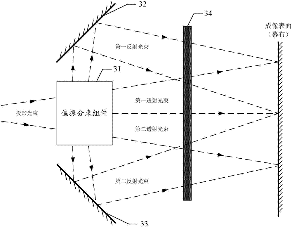
[0039] Different from the traditional idea of ​​dividing the projected beam into a transmitted beam and a reflected beam in the dual optical path polarization splitting method, the embodiment of the present invention divides the projected beam into four beams including two transmitted beams and two reflected beams.

[0040] Based on this principle, as image 3 As shown, the first embodiment of the present invention provides a polarization modulation device for stereoscopic projection light, including: a polarization beam splitting component 31, a first optical path direction adjustment component 32...


PUM


Abstract

The present invention is suitable for the technical field of projection display, and provides a stereoscopic projection light polarization modulation device. The stereoscopic projection light polarization modulation device comprises: a polarization beam splitting module configured to perform light beam splitting of a projection light beam carrying image information into two transmitting light beams and two reflection light beams, wherein polarization states of the two transmitting light beams are different, and polarization states of the two reflection light beam are also different; a first optical path direction regulation module configured to regulate a propagation direction of a first reflection light beam; a second optical path direction regulation module configured to regulate a propagation direction of a second reflection light beam; and a polarization state conversion module configured to perform polarization state modulation of some or all of the two transmitting light beams and the two reflection light beams and allow the two transmitting light beams and the two reflection light beams after modulation to have the same polarization state. Compared to a polarization light splitting mode of a dual optical path, the stereoscopic projection light polarization modulation device and method, and the stereoscopic image projection system can effectively reduce the optical path difference of the reflection light beams and the transmitting light beams and can greatly reduce the size of the whole device.

Description

technical field [0001] The invention belongs to the technical field of projection display, and in particular relates to a polarization modulation device and method for stereoscopic projection light and a stereoscopic image projection system. Background technique [0002] The principle of stereoscopic video viewing is that the left and right eyes of a person respectively receive the video images of the left and right eyes played in frame order, and then synthesize the video images of the left and right eyes through the brain to produce a stereoscopic effect. [0003] The current left and right eye image receiving technologies mainly include the left and right polarization splitting methods, the left and right shutter switch synchronization methods, and the left and right red and blue splitting methods, among which the left and right polarization splitting methods are more widely used. In the left and right polarization splitting methods, single optical path polarization split...

Claims


Application Information

Patent Timeline
Patent Type & Authority Applications(China)
IPC IPC(8): G02B27/26G03B21/28G03B21/14H04N13/337H04N9/31G02B30/25
CPCH04N9/3167G03B21/14G03B21/28G02B30/25
Inventor 周永业邓树端
Owner SHENZHEN TIME WAYING TECH
Learn More